Connecting-up 06.2006
6SE7087-6KP50 Siemens AG
7-8 Operating Instructions SIMOVERT MASTERDRIVES
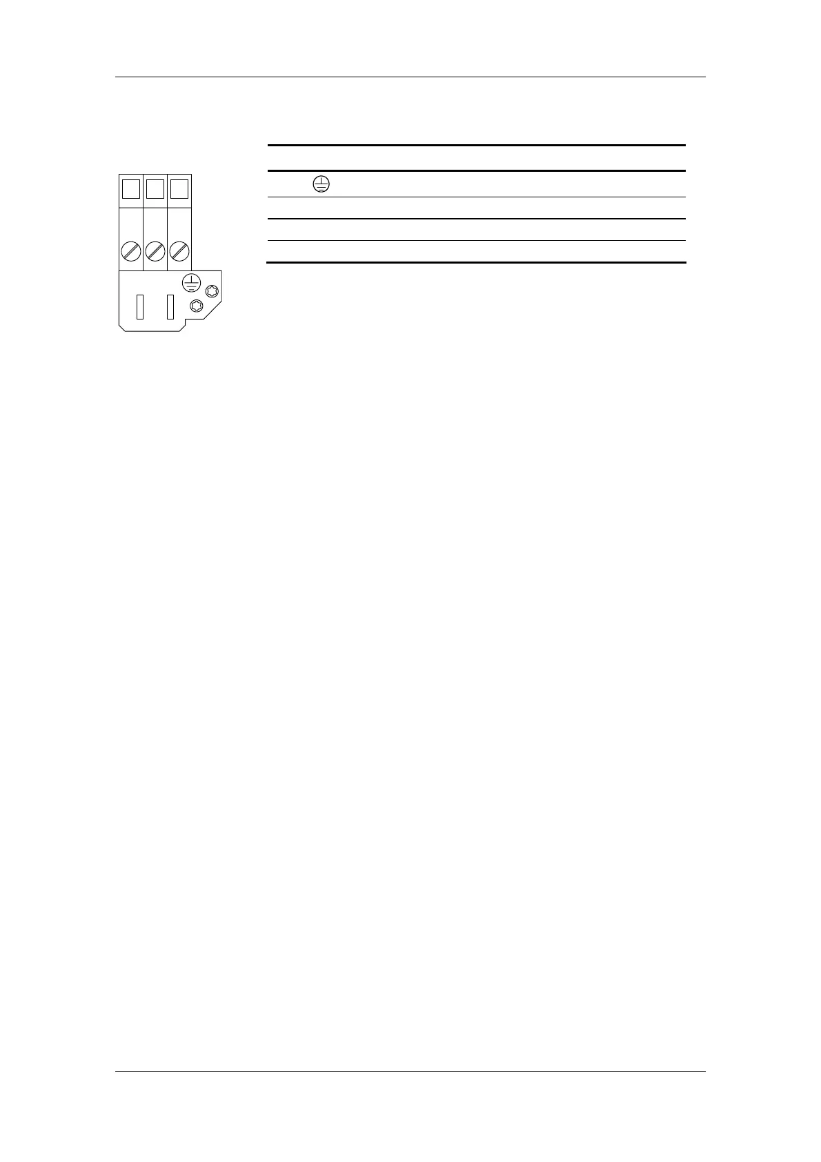
The motor connection is to a terminal block at the bottom of the unit.
Terminal Meaning Range
Protective conductor connection
U2 / T1 Phase U2 / T1 3AC 0 V - 480 V
V2 / T2 Phase V2 / T2 3AC 0 V - 480 V
W2 / T3 Phase W2 / T3 3AC 0 V - 480 V
Connectable cross-section:
Maximum cross-section: 50 mm² (AWG 1/0),
Minimum cross-section: 10 mm² (AWG 6)
PE terminal is at the bottom right of the shield plate.
Table 7-5 Motor connection
The motor cables must be dimensioned in accordance with VDE 298,
Part 2.
After installation of the connector, the shield of the motor cable must be
fixed to the shield plate through a large surface area.
X2 – Motor
connection ≥ 22 kW
U2 V2 W2
 Loading...


