Electrical Data
1.1 Definitions
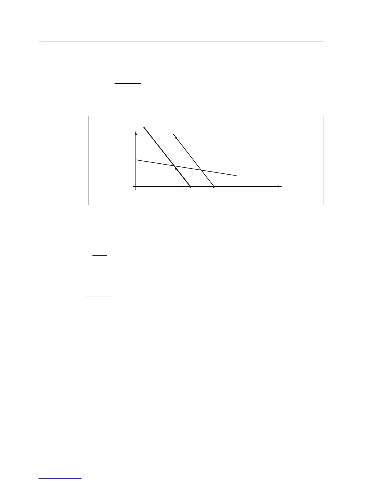
Calculating the new limiting torque with the new limiting characteristic
PRW
OLPLW
L1PRWQHZ
OLPLWQHZ
L1
•=
-
-
M
V
V
VV
M
The value M
limit
is read-off from the limiting characteristic for V
mot
(value at the rated speed).
33
0>1P@
3
0
OLPLW
Q>530@
Q
Q
6.
1HZFRQYHUWHURXWSXWYROWDJH8
PRWQHZ
7KHUPDO
OLPLWLQJFKDUDFWHULVWLF
Q
3
0
OLPLWQHZ
&RQYHUWHURXWSXWYROWDJH8
PRW
1
Figure 1-4 The voltage limiting characteristic is shifted from V
mot
to V
mot new
P1 The voltage limiting characteristic, specified for V
mot
intersects with the x axis (speed) at n
1
[RPM].
P2 The point where the voltage limiting characteristic intersects with the x axis is shifted from n
1
to n
2.
PRW
QHZPRW
[]
12
•=
RPM
V
V
nn
P3 Read-off M
limit
at the voltage limiting characteristic specified for V
mot
.
Calculating M
limit, new
:
PRW
OLPLW
L1PRWQHZ
OLPLWQHZ
L1
•=
-
-
M
V
V
VV
M
P4 M
limit, new
The shifted voltage limiting characteristic is obtained with points P2 and P4.
General Section for Synchronous Motors
1-6 Configuration Manual, (PJAL), 11.2005 Edition, 6SN1 197-0AD07-0BP4
 Loading...


