Installation 10.98
6SE7087-6KP50 Siemens AG
5-2 Operating Instructions SIMOVERT MASTERDRIVES
Mounting
surface
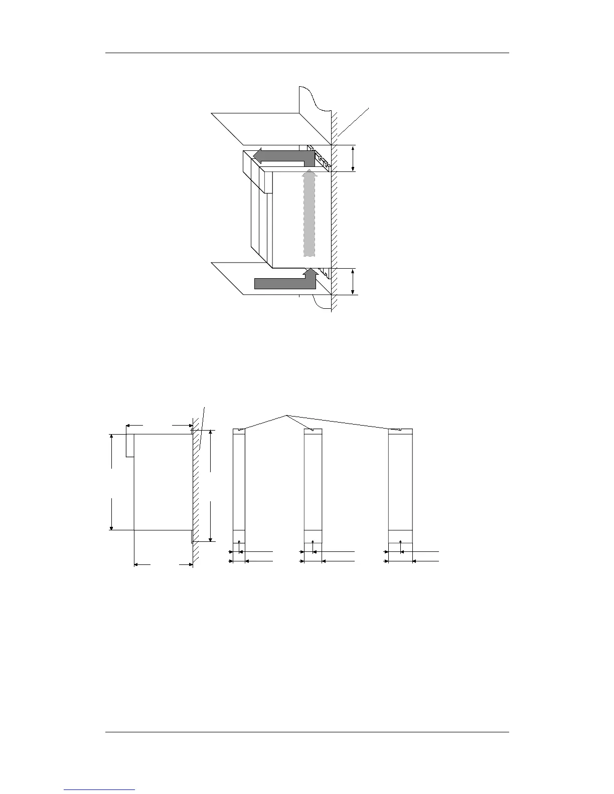
100 mm
100 mm
Cooling air
Fig. 5-1 Minimum clearances for cooling
The unit is mounted directly to a mounting surface. Fixing is by means
of two or four M5 screws.
Side view Front view (without front cover)
22.5 mm
220 mm
360 mm
Mounting surface Slots
for screws M5
414 mm
45 mm
250 mm
33.75 mm
67.5 mm
45 mm
90 mm
0.75 kW 1.5 / 2.2 kW 4.0 kW
Fig. 5-2 Dimension drawings for housings up to 90 mm wide
Installation