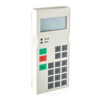
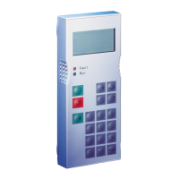
OP1S Operator Control Panel
477 459 4070 76 J AA-74 Siemens AG
8 Operating Instructions SIMOVERT MASTERDRIVES
Key Meaning Function
+/-
Sign key
• For changing the sign so that negative values can be
entered
0
...
9
Number keys
• Numerical input
Table 3-1 Operator control elements of the OP1S
3.2 Operating display
After run-up of the OP1S, the following operating display appears.
0.0 A 0 V 00
# 0.00 min-1
* 0.00 min-1
Ready
Example of an operating display in
the "Ready" state
The values shown in the operating display (except for slave number, 1st line on the far
right) can be specified by means of parameterization.
1st line left in the example "Output current"
1st line right in the example "DC link voltage"
2nd line actual value in the example, "Actual speed" (only a visualization
parameter)
3rd line setpoint in the example "Speed setpoint"
4th line in the example "Operating state"
In the operating display, the actual value is indicated with "#“ and the setpoint with "*“.
In addition to the operating display on the display unit, the operating state is indicated by
the red and green LEDs as follows:
Flashing Continuous
Red LED Warning Fault
Green LED Ready Operating
Table 3-2 Operating displays