Installing
3.3 Terminal strips on CU240B-2 Control Units
CU240B-2 and CU240E-2 Control Units
Compact Operating Instructions, 04/2015, A5E35792002B AA
11
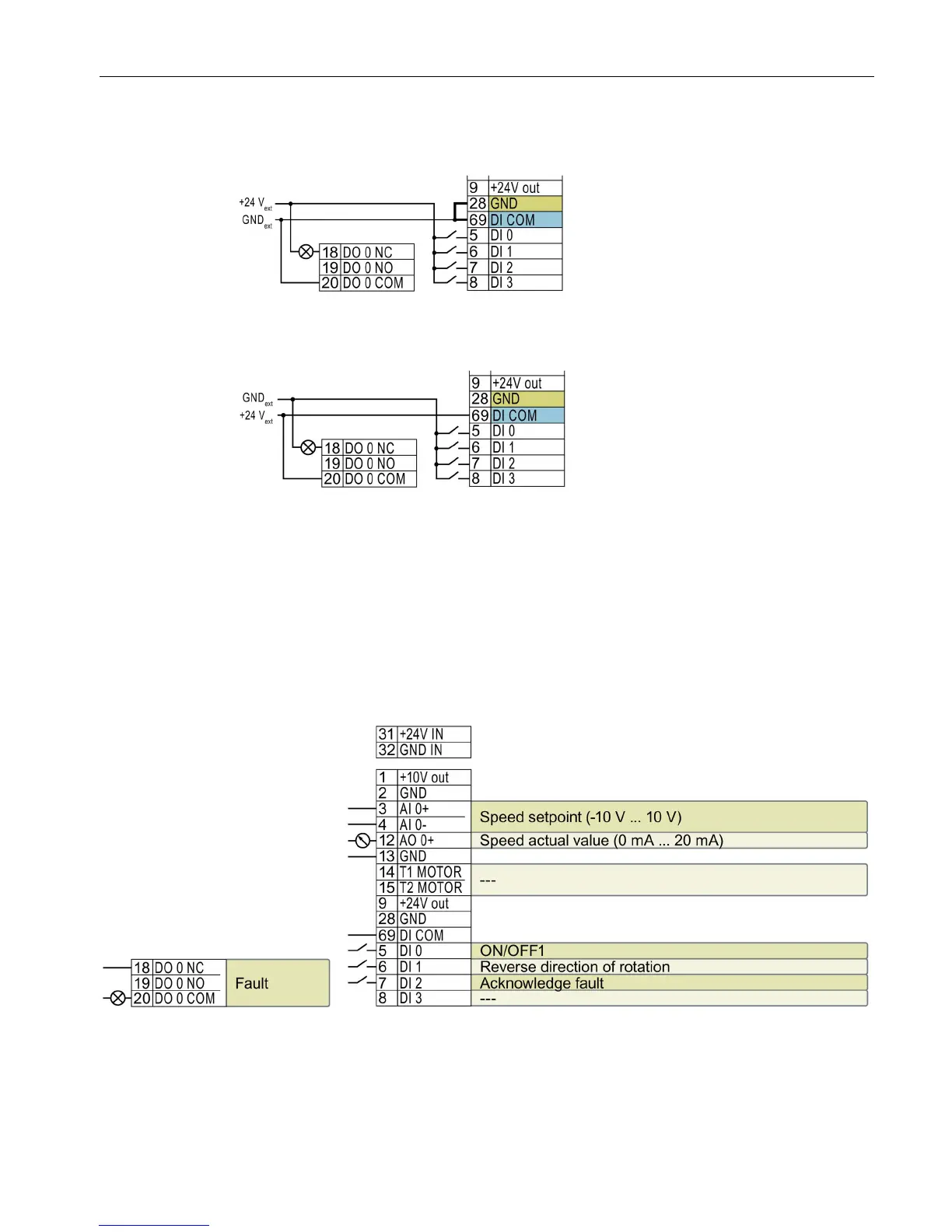
Additional options for wiring the digital inputs
Connecting P-switching contacts with an external
You must remove the jumper b
terminals 28 and 69 if it is necessary to
have electrical isolation between the
external power supply and the internal
inverter power su
pply.
Connecting M-switching contacts with an external
It is not permissible that terminals 28 and
69 are connected with one a
Factory setting of the terminal strip on the CU240B-2
The factory setting of the terminals depends on whether the Control Unit has a PROFIBUS /
PROFINET interface.
Control Units with USS interface
The fieldbus interface is not active.
Speed setpoint (main setpoint): p1070[0] = 755[0]
Figure 3-2 Factory settings of the CU240B-2 Control Unit

 Loading...


