Connecting up, switching on
4.2 Line, motor and DC link connection
Power Module PM330
Hardware Installation Manual, 10/2016, A5E32844552B AD
35
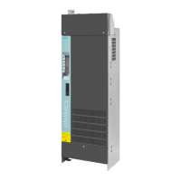
The diagram shows the layout
of line and motor terminals a
nd
Optionally, the line connection
can be established using the
"Installation set for line
-side
cable connection, left", see
In-
-side cable
(Page 41)
Tightening torques for the line,
motor and PE terminals (M12):
50
Nm
The cable entry protection (
①)
must be broken out correspon
d-
ing to the diameter of the cable
to be introduced.
After connecting, the covers of
the line and motor terminals
must be reinstalled (tightening
torque: 6
Nm).
 Loading...
