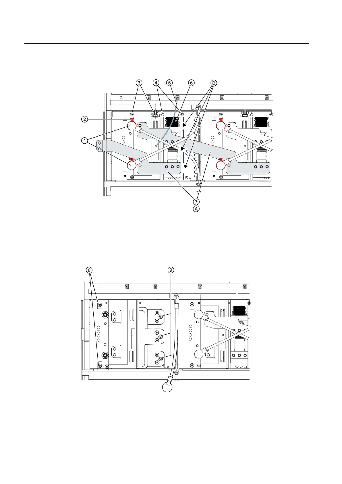
8. Withdraw the bypass ⑥ a little. Pull the connection cable at the rear of the bypass. Pull the
bypass out completely.
Figure 9-7 Removing a power cell, steps 1 to 8
9. Remove the two screws (M5 x 25) ⑧ between the heat sink and the housing of the capacitor
bank.
10.Remove all of the screws (M8 x 20) ⑨ between the capacitor busbar and the IGBT module.
11.Now remove the IGBT module by withdrawing it to the front.
Figure 9-8 Removing a power cell, steps 9 to 11
Maintenance
9.7 Repair
SINAMICS PERFECT HARMONY GH150 6SL38253AE412AA1-Z
124 Operating Instructions Rev.201910281231 EXAMPLE
 Loading...


