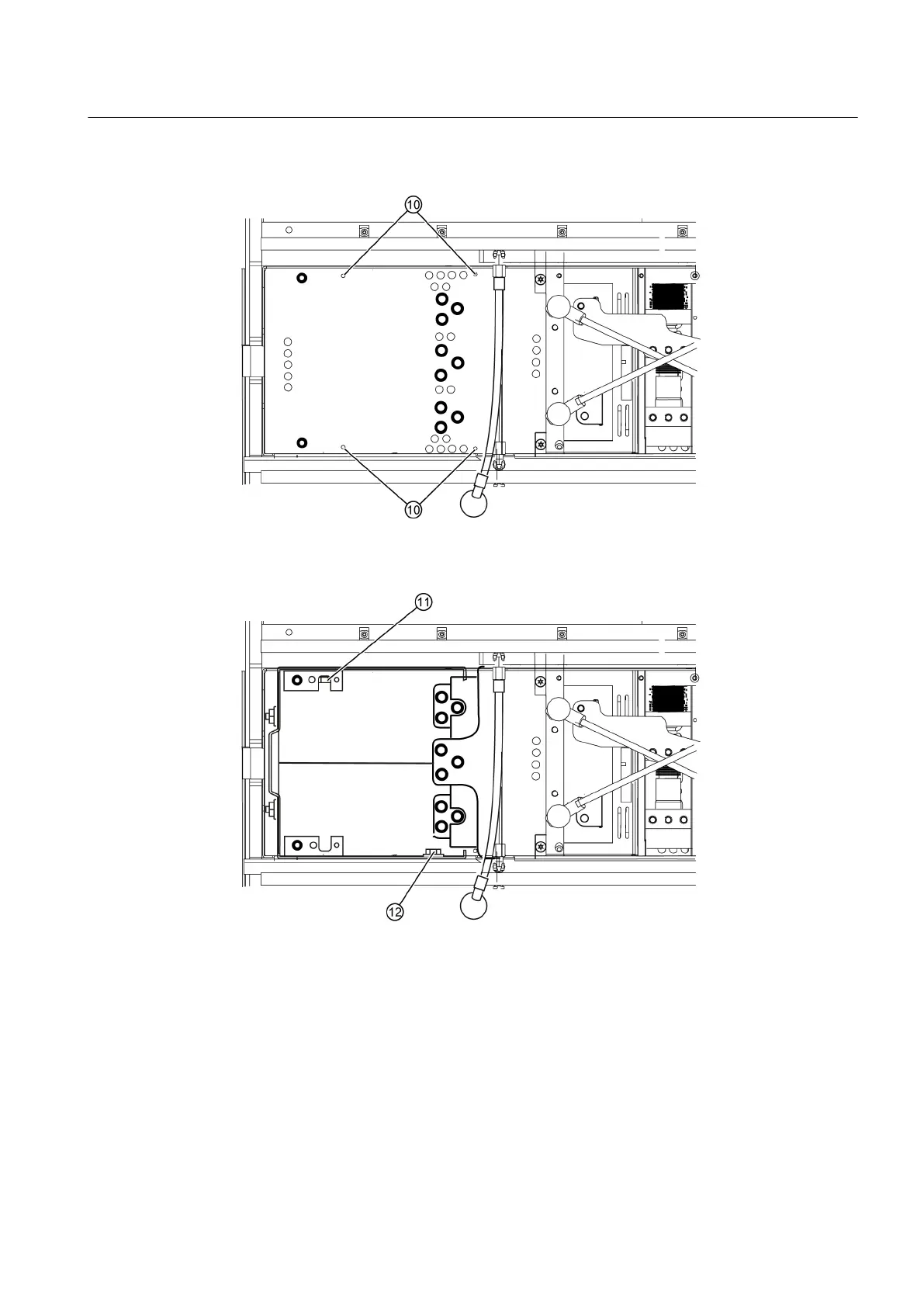
12.Remove the screws ⑩ (M4 x 10). Withdraw the plate towards the front.
Figure 9-9 Removing a power cell, step 12
13.Loosen the bolted connection ⑪ (M8 x 30). Remove the screw ⑫ (M8 x 16) of the capacitor
bank.
Figure 9-10 Removing a power cell, step 13
14.Withdraw the capacitor bank towards the front.
Maintenance
9.7 Repair
SINAMICS PERFECT HARMONY GH150 6SL38253AE412AA1-Z
Operating Instructions Rev.201910281231 EXAMPLE 125
 Loading...


