S5-95U, SINEC L2 Data Transfer with PLC-to-PLC Connections
6 Data Transmission Using PLC-to-PLC
Connections
This chapter provides you with the following information:
• How this type of data transmission functions in principle
• How to communicate with the CP 5430 communications processor
• How to set parameters for the programmable controllers
• How to program with STEP 5 for this type of data transmission (examples)
6.1 Features of the PLC-to-PLC Connections
• You use PLC-to-PLC connections to connect active stations.
• You can set parameters in DB1 for a maximum of 31 PLC-to-PLC connections.
• You use the integral function blocks L2-SEND and L2-RECEIVE to communicate via PLC-to-PLC
connection. L2-SEND and L2-RECEIVE are described in detail in chapter 5.
• For L2-SEND you need to specify the following parameters:
- The destination programmable controller as the job number
The job number is identical to the destination station address on the SINEC L2 network.
- The data to transmit
• For L2-RECEIVE you need to specify the following parameter:
- The source programmable controller as the job number.
(The job number is identical to the source station address on the SINEC L2 network.)
• Please note that
- a specific status byte ‘Transmit’ STBS belongs to L2-SEND and each of the job numbers
- a specific status byte ‘Receive’ STBR belongs to L2-RECEIVE and each of the job numbers
• You can transmit or receive a maximum of 242 bytes of data per job.
• You can transmit in parallel to several stations.
• You can receive in parallel to several stations.
• You can transmit faster using PLC-to-PLC connections than using standard connections.
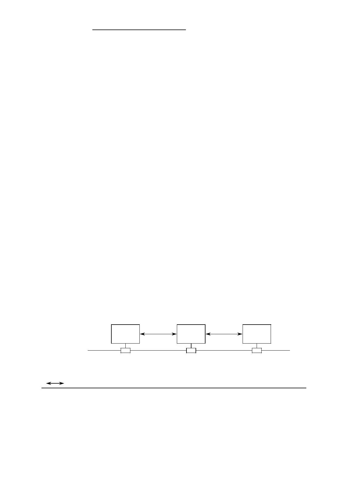
Figure 6-1 shows a possible hardware configuration ( section 1.5) for the PLC-to-PLC
connections. All examples in section 6.3 refer to PLC 1 and PLC 2 in this configuration.
Figure 6-1. Example: Hardware Configuration for PLC-to-PLC Connection
Bus
Passive
stations
PLC to PLC connection
Active
stations
CP 5430 S5-95U
(PLC 1)
S5-95U
(PLC 2)
. . .
PLC-PLCPLC-PLC
none
EWA 4NEB 812 6112-02
6-1
 Loading...


