S5-95U, SINEC L2 System Description
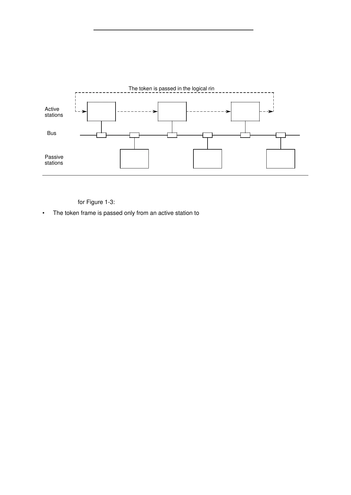
A network normally contains several active and several passive stations. Figure 1-3 shows a net-
work with three active and three passive L2 stations.
Figure 1-3. Bus Accessing Procedure
2
101 102
1 3
100
a
a
a
a
a
a
a
a
a
a
a
a
a
a
a
a
a
a
a
a
a
a
a
a
a
a
a
a
a
a
a
a
a
a
a
a
a
a
a
a
Active
stations
a
a
a
a
a
a
a
a
a
a
a
a
a
a
a
a
a
a
a
a
a
a
a
a
a
a
a
a
a
a
a
a
a
a
a
a
a
a
a
a
Passive
stations
Bus
The token is passed in the logical ring
Explanations for Figure 1-3:
• The token frame is passed only from an active station to another.
Stations 1, 2 and 3 are active. The token frame is passed on as follows:
1 2 3 1 2 ...
• One token cycle includes passing the token three times:
1 2 3 1.
• Stations 100, 101 and 102 are passive.
• Stations addresses 0, 4 to 99, and 103 to 126 are not assigned.
• Active stations can be assigned addresses in the range 1 to 31.
• Passive stations can be assigned addresses in the range 1 to 126.
• It is not absolutely necessary to assign the station addresses in ascending order.
Based on the mode of operation of the SINEC L2, two special cases can be deduced:
1) If only one station is active and all others are passive, the bus functions according to the
master-slave principle.
2) If all stations are active, a token passing procedure is present.
EWA 4NEB 812 6112-02
1-5
 Loading...


