Data Transfer with PLC-to-PLC Connections S5-95U, SINEC L2
6.3 Programming Example for Data Transmission via PLC-to-PLC
Connections Using Standard Function Blocks
This section explains the structure of the control programs for two programmable controllers.
Example:
PLC 1 and PLC 2 are to exchange data with one another, i.e., they will transmit and receive. Refer
to section 6.1 for the description of the hardware configuration.
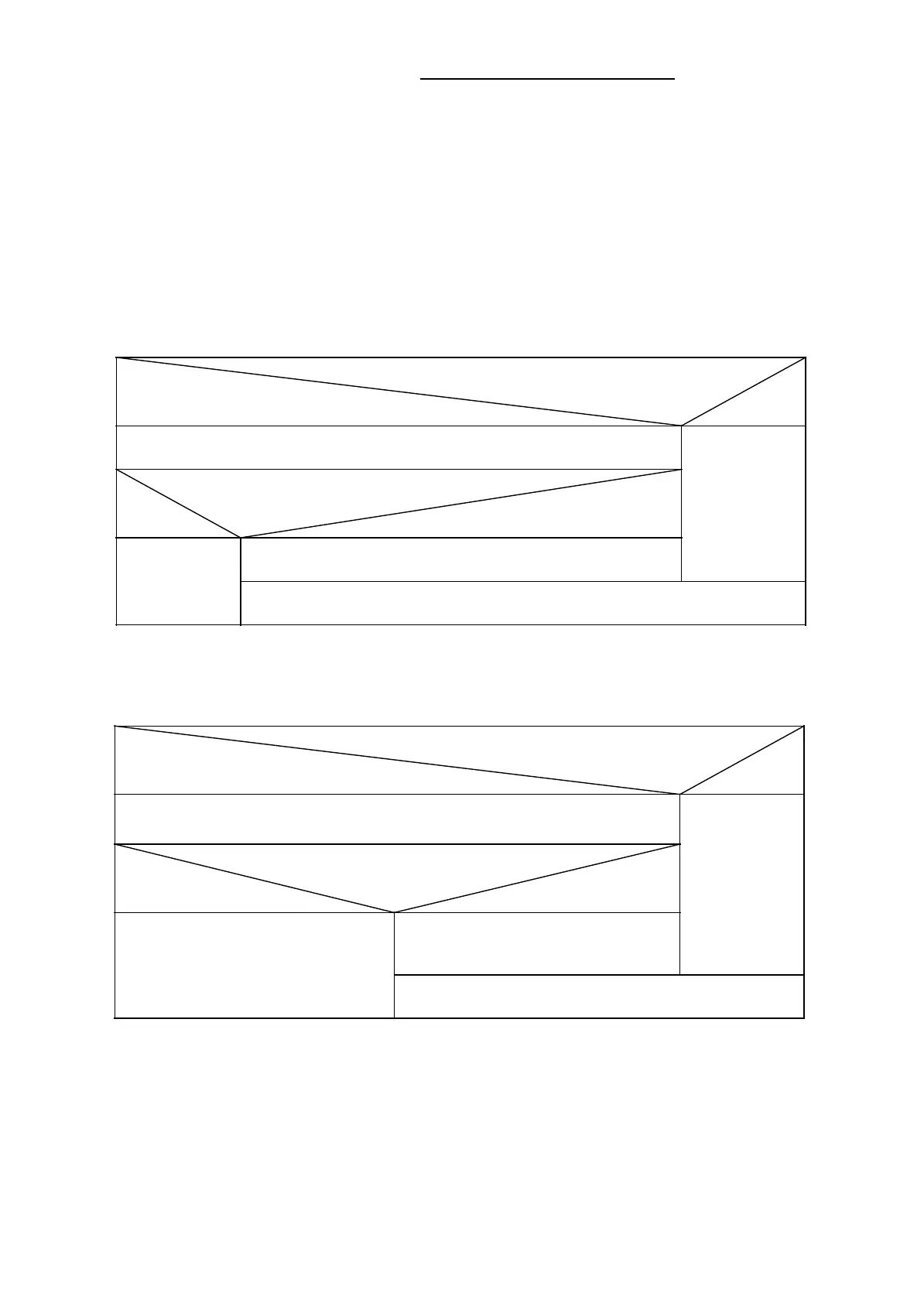
The control program in FB105 for transmitting data is structured as illustrated below.
Wish to transmit? (Transmit trigger bit set by the user?)
yes
no
Call up of function block L2-SEND
Has PAFE message or STBS error occurred?
yes no
Confirm transmit request. (The program resets the transmit trigger bit.)
Transmit request is
repeated automati-
cally (call up of L2-
SEND)
End
The control program in FB15 for receiving data is structured as illustrated below.
Receive enabled and “Receive viable”? (Receive enable bit set by the user
and bit 0 of STBR =1?)
yes no
Call up of function block L2-RECEIVE; data are fetched.
Receive request is repeated automatically
(call up of L2-RECEIVE)
Has PAFE message or STBR error occurred?
yes no
Confirm receive request. (The program resets the
receive enable bit.)
End
6-6
EWA 4NEB 812 6112-02
 Loading...


