Installation Guidelines S5-95U, SINEC L2
2.3 Linking Bus Segments with the L2 Repeater
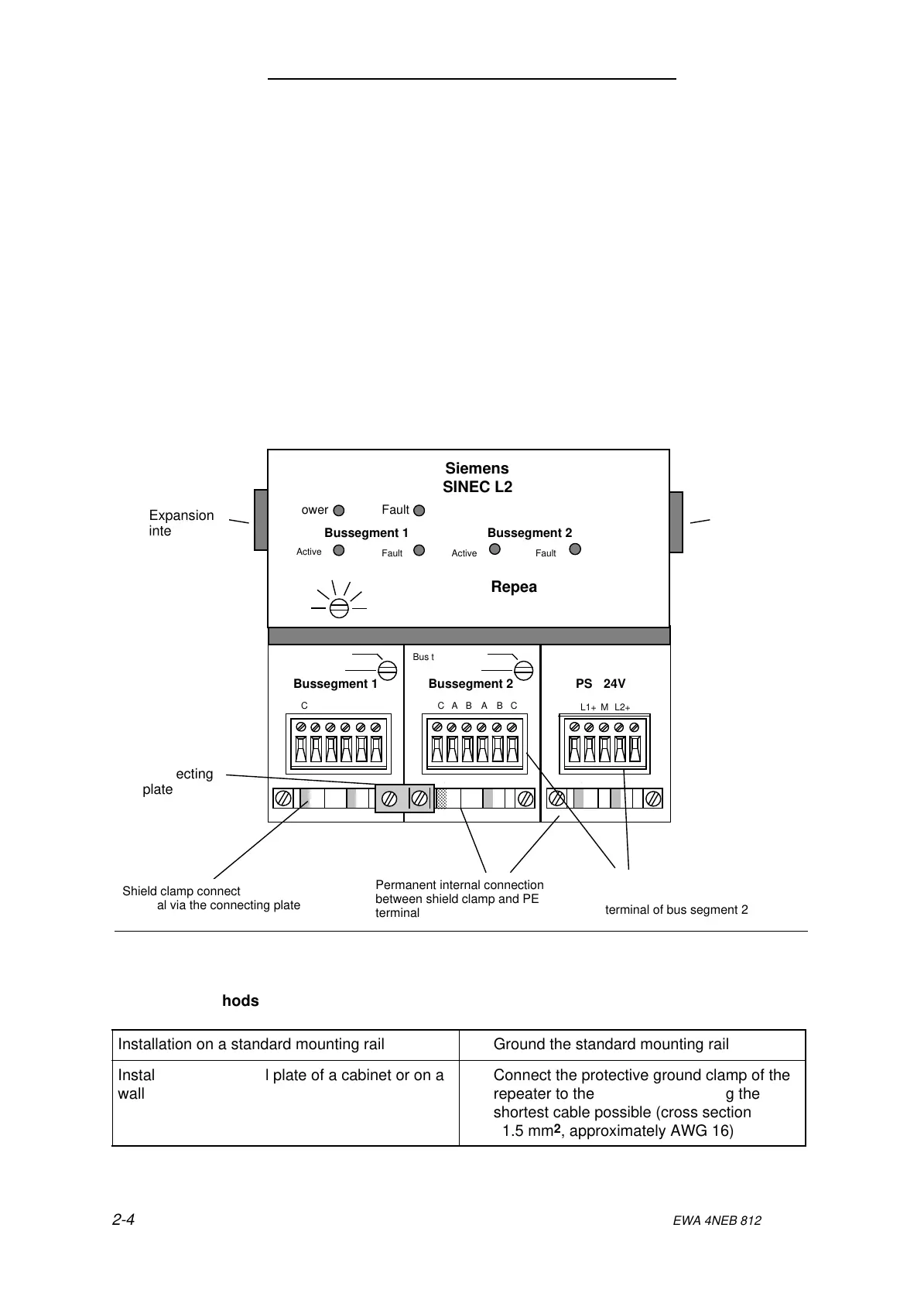
2.3.1 Electrical Design of the SINEC L2 Repeater RS 485
Voltage Potentials for a Correct EMC Installation of the L2 Repeater
• Bus segment 1 and bus segment 2 are electrically isolated from each other.
• Bus segment 2 and the power supply have a common reference potential.
• The reference potential (M terminal) and the protective ground conductor (PE terminal) are not
connected to one another.
• All the shield clamps are connected to the protective ground conductor (PE terminal) at the
factory. The clamps for the power supply and bus segment 2 are connected internally to the
PE terminal. The connection between bus segment 1 and the PE terminal can be removed
(remove connecting plate between bus segments 1 and 2).
• Terminal C (“C” stands for common) is not needed to connect the two-wire SINEC L2 bus
cable.
Figure 2-5. Voltage Potentials for the SINEC L2 Repeater RS 485
a
a
a
a
a
a
a
a
a
a
a
a
a
a
a
a
a
a
a
a
a
a
a
a
a
a
a
a
a
a
a
a
a
a
a
a
a
a
a
PS 24V
Repeater
RS 485
Bit rate
Power Fault
Active
Fault Active Fault
Bussegment 1 Bussegment 2
a
a
a
a
a
a
a
a
a
a
a
a
a
a
a
a
a
a
a
a
a
a
a
a
a
a
a
a
a
a
a
a
a
a
a
a
a
a
a
a
a
a
a
a
a
a
a
a
a
a
a
a
a
a
a
a
a
a
a
a
a
a
a
a
a
a
a
a
a
a
a
a
a
a
a
a
a
a
a
a
a
a
a
a
a
a
a
a
a
a
a
a
a
a
a
a
a
a
a
a
a
a
a
a
a
a
a
a
a
a
a
a
a
a
a
a
a
a
a
a
a
a
a
a
a
a
a
a
a
a
a
a
a
a
a
a
a
a
a
a
a
a
a
a
a
a
a
a
a
a
a
a
a
a
a
a
a
a
a
a
a
a
a
a
a
a
a
a
a
a
a
a
a
a
a
a
a
a
a
a
a
a
a
a
a
a
a
a
a
a
a
a
a
a
a
a
a
a
a
a
a
a
a
a
a
a
a
a
a
a
a
a
a
a
a
a
a
a
a
a
a
a
a
a
a
a
a
a
a
a
a
a
a
a
a
a
a
a
a
a
a
a
a
a
a
a
a
a
a
a
a
a
a
a
a
a
a
a
a
a
a
a
a
a
a
a
a
a
a
a
a
a
a
a
a
a
a
a
a
a
a
a
a
a
a
a
a
a
a
a
a
a
a
a
a
a
a
a
a
a
a
a
a
a
a
Expansion
interface
Internal connection between M
terminal of the power supply and C
terminal of bus segment 2
Shield clamp connected to PE
terminal via the connecting plate
Permanent internal connection
between shield clamp and PE
terminal
Grounding Methods
Installation on a standard mounting rail Ground the standard mounting rail
Installation on a metal plate of a cabinet or on a
wall
Connect the protective ground clamp of the
repeater to the grounding rail using the
shortest cable possible (cross section
1.5 mm
2
, approximately AWG 16)
2-4
EWA 4NEB 812 6112-02
 Loading...


