.
.
Start-Up, Tests, and Diagnostics
S5-95U,
SINEC
L2
.,
,.
3.1
Design and
Mode of Operation of the Programmable Controller
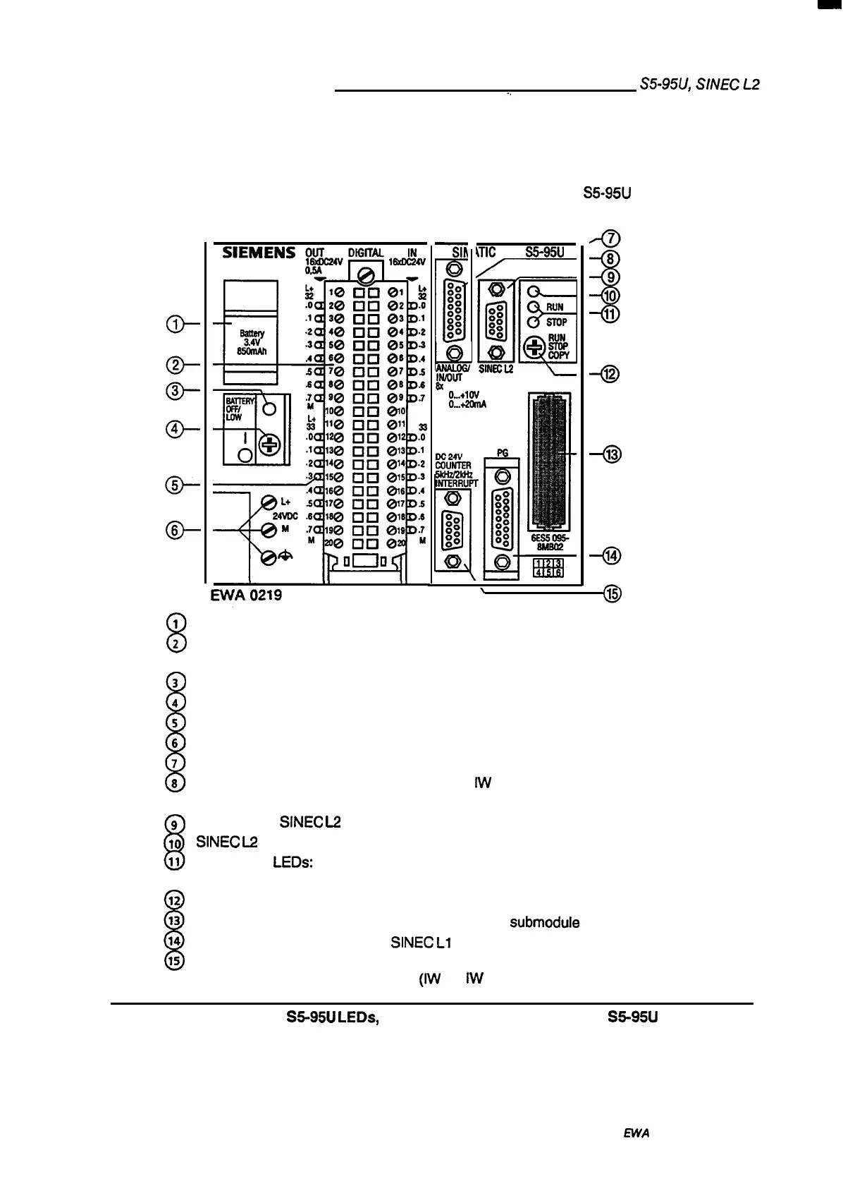
Figure 3-1 shows all the displays, operator controls and interfaces of the S5-95U
(Order No. 6ES5095-8MB@
-
cD-
8
1
2
1
3
4
5
6
7
8
8
9
10
11
8
12
13
14
15
Y
D
0
0
0
0
0
0
0
0
0
0
0
0
:0
h
—
pAL#
8X
O..*1W
lx
O...+lw
o..+2omA
\TIC
85-95U
m
o
a
0:
RUN
0
0
0
0
STOP
:
+~w
SINEC12
DC24V
m
mutnm
5kHzfzkltz
INTERRUPT
III!l
a
00
0:
D
0
0
0
0
0
0
0
0
00
0
0
0
0
0
0
:
m’
Battery compartment
Front panel connector
for digital inputs (1 32.0 to 133.7) and
for digital outputs (Q 32.0 to Q 33.7)
Battery low LED
ON/OFF switch
LED display for digital inputs and outputs
Terminals for connecting the power supply
Cable connector for S5-1OOU modules
Interface
for analog inputs (IW 40 to
IW
54) and
for analog outputs (QW 40)
Interface for
SINEC
L2
bus
SINEC
L2
bus fault LED
RUN/STOP
LEDs:
The green
indicates the “STOP” mode.
RUN/STOP/COPY switch
Receptacle for an EPROM or
Interface for a PG, PC, OP or
LED indicates the “RUN” mode, the red LED
EEPROM memory
submodule
SINEC
L1
bus
interface
for interrupt inputs (1 34.0 to 34.3) and
for counter inputs
(NV
36, IW 38)
Figure 3-1. S5-95U LEDs, Controls, and Interfaces of the S5-95U
3-2
EWA
4NEB 8126112-02
 Loading...


