Programming and Operating — Turning Page 14 808D ADVANCED
Tool Setup
s
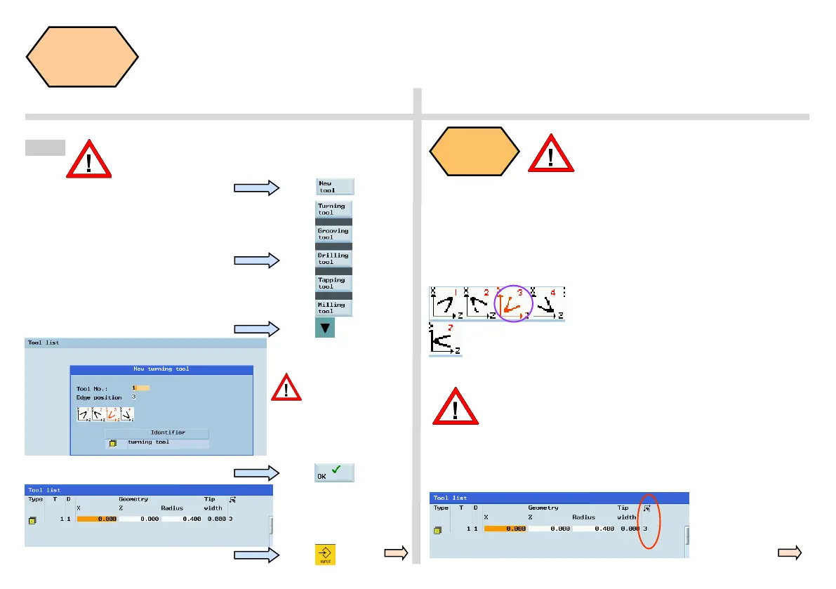
SEQUENCE
Press the “New tool” SK on the PPU.
Press the “OK” SK on the PPU
Press the “Input” button on the PPU
Enter “1” at “Tool No.”
Enter “3” at “Edge
position”.
The correct “Edge
position” selection
directly determines the
correct tool compensation
which will be described in
the next unit.
Tool edge
position
code
Principle of correct tool edge position
code selection: Select the correspond-
ing tool edge position code according to
actual tool point direction!
Observe the relationship between the tool point direction and the positive
direction of the X axis and the Z axis.
Find the corresponding position relationship in the figure below and enter
the number in “Edge position”; the red coordinate in the purple circle is the
selected position code.
Note that the tool tip direction here is the direction after
the correct tool offset, not only the direction in tool load-
ing. And the correct of tool edge position code directly
affects the tool tip radius compensation!
The tool edge position code can also be changed in the
position showed in the figure.
Step 2
The range of tool numbers which can be created by
this system is 1 ~32000. The machine can be loaded
with a maximum of 64 tools / 128 tool edges.
Select the type of required tool.
Enter the “Radius” and/or
“Tip width” as required.
Note: Not every tool has eight position codes. All the options are shown above.
As to “turning tool” and “grooving tool”, 808D
ADVANCED provide 4 edges (#1~4) which are shown
on the left figure.
As to “drilling tool” and “tapping tool ”, 808D
ADVANCED provide only 1 edge (#7) which is also
shown on the left figure.

 Loading...


