808D ADVANCED Page 31 Programming and Operating — Turning
Create Part
Program
Part 1
s
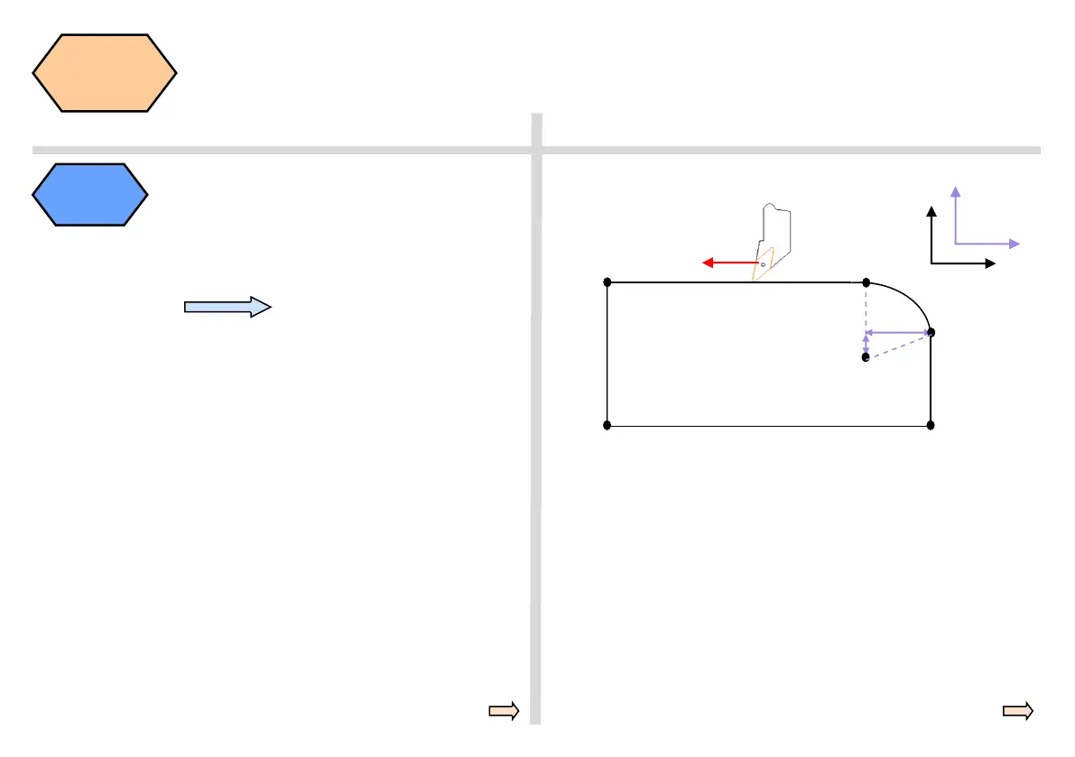
(K)-35
SP
X50, Z0
X0, Z0
(I) -12
EP
SP = start point of circle
CP = center point of circle
EP = end point of circle
I = defined relative increment from start point to center point in X
K = defined relative increment from start point to center point in Z
Z-130
X75, Z-35
Z-130, X0
Z
X
CP
K
I
G2 = define circle direction in traversing direction = G2 clockwise
G3 = define circle direction in traversing direction = G3 counter-clockwise
Determine tool radius of T1 D1
Turning
circles and
arcs
The circle radius
shown in the ex-
ample on the right
can be produced
with the specified
part program code.
When milling circles
and arcs, you must
define the circle
center point and the
distance between
the start point / end
point and the center
point on the relative
coordinate.
When working in the
XZ coordinate
system, the
interpolation
parameters I and K
are available.
N5 G17 G90 G500 G71
N10 T1 D1
N15 S5000 M3 G95 F0.3
N20 G00 X0 Z2
N25 G01 Z0
N30 G42 X50
N45 G03 X75 Z-35 I-12 K-35
N50 G01 Z-130
N60 G40 X120 Z-140
N35 G00 X300 Z500
Note:
N45 can also be written as follows
N45 G03 X75 Z-35 CR=37
Tool motion direction
BASIC THEORY
Two common types of defining circles
and arcs:
①:G02/G03 X_Z_I_k_;
②:G02/G03 X_Z_CR=_;
Arcs ≤180º,CR is a positive number
Arcs >180º,CR is a negative number

 Loading...


