Programming and Operating — Turning Page 36 808D ADVANCED
Create Part
Program
Part 2
s
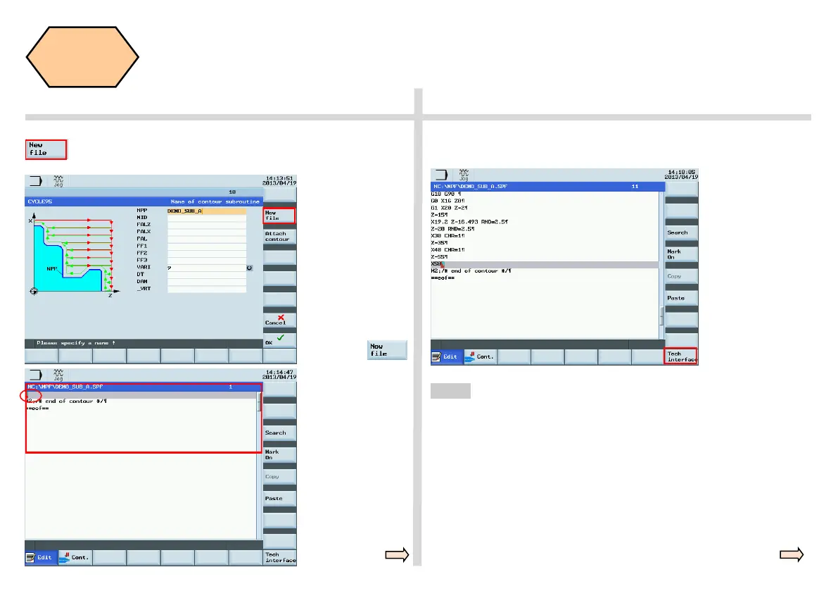
Make sure the
cursor is in the
editing position
(shown in the
figure on the left).
After opening the contour data setting window, please make the following
settings:
Enter appropriate
coordinates based
on the data from the
technical drawing.
By selecting the “New file” SK, the contour turning data can be
inserted into Sub Program File (.SPF). You can edit and change it
when selected. The sequence is as follows:
Open the cycle data
setting window and
enter the name of
the contour
subprogram.
Press “New file ” on
the PPU to create
contour information
in the .SPF file. The
cursor moves to the
contour editing posi-
tion automatically.
BASIC THEORY
The radii and the chamfer
can be produced using
the contour editor, in
conjunction with the
roughing or finishing
cycles.
RND and CHR/CHF can
be found in the additive
description of the T
contour.
RND = Radii
CHR = Chamfer
(specified side length of isosceles triangle with
chamfer as base line)
CHF = Chamfer
(specified base line length of isosceles triangle
with chamfer as base line)
Radius and chamfers
Step 2

 Loading...


