Descriptions of the PLC subroutines
3.13 Subroutine 40 - AXIS_CTL (controlling the spindle and axes)
PLC Subroutines Manual
Operating Instructions, 12/2012, 6FC5397-2EP10-0BA0
43
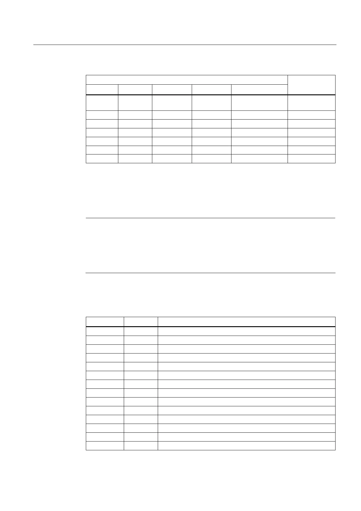
Encoding the hardware limit switches
E_Key _1LMTp _2LMTp _3LMTp Direction
Result
0 1 1 1 - EMERGENCY
STOP active
0 0 1 1 DB3900.DBX4.7 1st + over limit
0 0 1 1 DB3900.DBX4.6 1st - over limit
0 0 0 1 DB3901.DBX4.7 2nd + over limit
0 0 0 1 DB3901.DBX4.6 2nd - over limit
0 0 0 0 DB3902.DBX4.7 3rd + over limit
0 0 0 0 DB3902.DBX4.6 3rd - over limit
In the hardware solution above, the feed stop signals for all axes (for example, disconnect
the terminal 65 of the SINAMICS V60 via a relay) can be activated via the hardware limit
switches when any of the hardware limits is reached or an EMERGENCY STOP happens.
You can check the information of the PLC diagnostics from the encoding of the hardware
limit switches shown in the table above, and identify the cause (Emergency Stop button or a
hardware limit switch of an axis) of the EMERGENCY STOP signal.
Note
When using the hardware solution, you must take below information into consideration:
You must assign the axes one by one; for example, X axis, Z axis, spindle or X axis, Y
axis, Z axis, spindle. You must not assign the axes like X axis, Y axis, spindle, Z axis.
You must set constant "1" (i.e. SM0.0) to the input signals of the hardware limits for
undefined axes; otherwise, the hardware limits of the undefined axes can be activated.
Local variable definition
Table 3- 5 Inputs
Name Type Description
NODEF WORD Reserved word
DrvEn_65 BOOL Drive enable signal from AXIS_CTL (SBR40)
Drv1_RDY BOOL Ready signal of the 1st drive, reserved
1)
Drv2_RDY BOOL Ready signal of the 2nd drive, reserved
1)
Drv3_RDY BOOL Ready signal of the 3rd drive, reserved
1)
OPTM BOOL Brake release switch (NO), used for drive optimization, reserved
_1LMTp BOOL 1st axis hardware limit switch + (NC)
2)
_1LMTn BOOL 1st axis hardware limit switch - (NC)
_1REF BOOL 1st axis reference cam (NO)
_2LMTp BOOL 2nd axis hardware limit switch + (NC)
2)
_2LMTn BOOL 2nd axis hardware limit switch - (NC)
_2REF BOOL 2nd axis reference cam (NO)
_3LMTp BOOL 3rd axis hardware limit switch + (NC)
2)
_3LMTn BOOL 3rd axis hardware limit switch - (NC)

 Loading...


