Descriptions of the PLC subroutines
3.13 Subroutine 40 - AXIS_CTL (controlling the spindle and axes)
PLC Subroutines Manual
44 Operating Instructions, 12/2012, 6FC5397-2EP10-0BA0
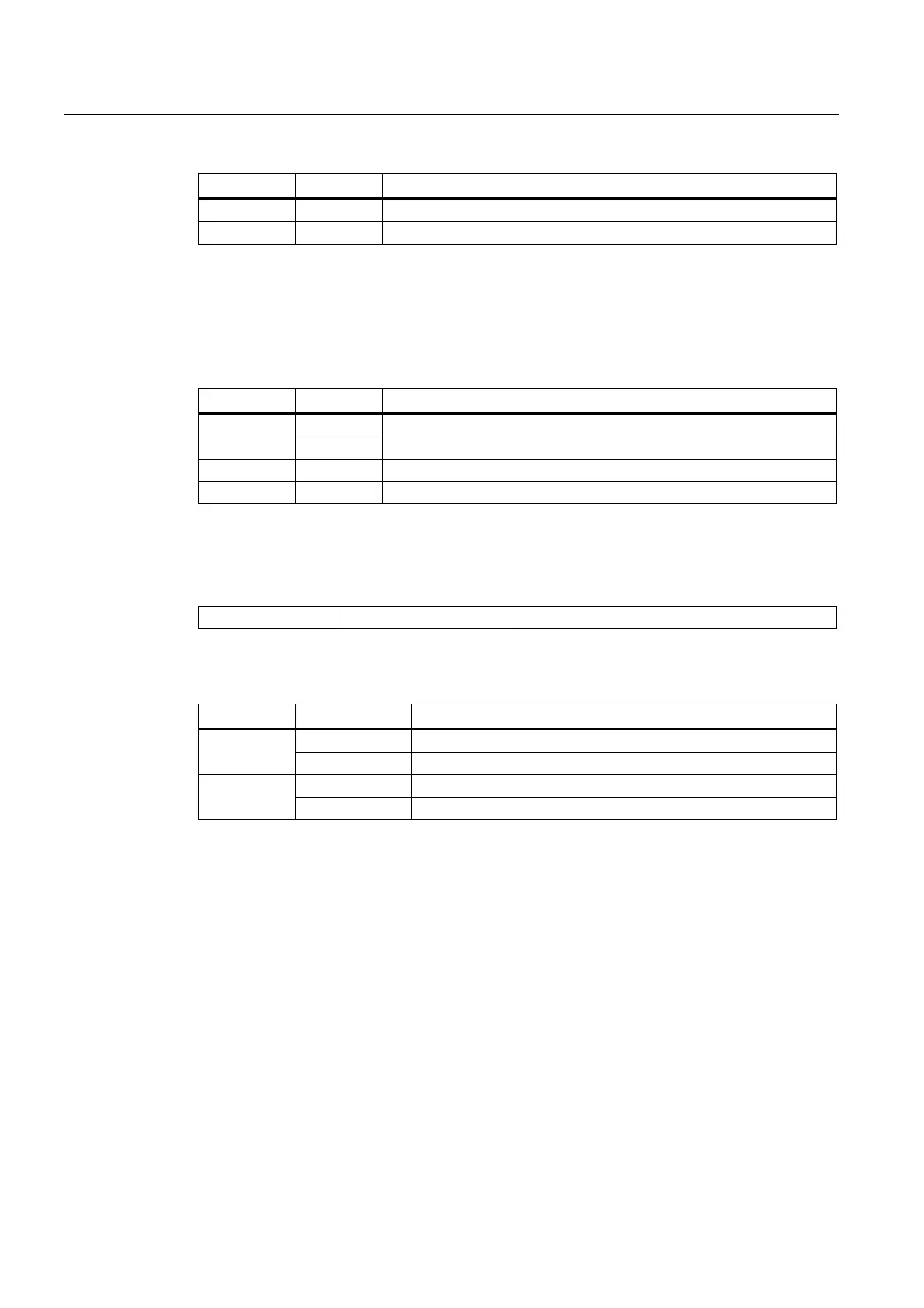
Name Type Description
_3REF BOOL 3rd axis reference cam (NO)
_4REF BOOL Reserved
1)
The PLC does not need to process the drive ready signals and alarm signals received from the
SINAMICS V60 because the SINUMERIK 808D has already processed these signals.
2)
The hardware limit + is used for the input if there is only one hardware limit switch or when the
hardware solution is used.
Table 3- 6 Outputs
Name Type Description
_1BRK BOOL 1st brake release output (high active, reserved)
1)
_2BRK BOOL 2nd brake release output (high active, reserved)
1)
_3BRK BOOL 3rd brake release output (high active, reserved)
1)
OVlmt BOOL Over-distance output (active at any hardware limit, high active )
1)
Motor brakes are controlled by the SINAMICS V60 drives themselves.
Assigned global variables
SP_CMD M138.1 Spindle start command (CW or CCW)
Relevant PLC machine data
No. Value Description
1 Overtravel employs the hardware solution 14512 [18].6
0 Overtravel employs the PLC solution
1 Each axis has only one hardware limit switch 14512 [18].7
0 Each axis direction has an hardware limit switch
 Loading...


