PLC sample applications
5.1 PLC sample application (turning)
PLC Subroutines Manual
80 Operating Instructions, 12/2012, 6FC5397-2EP10-0BA0
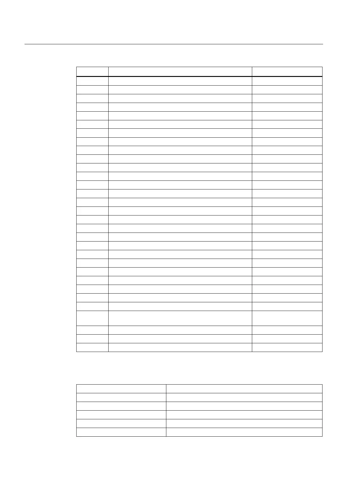
Signal Description Remark
I3.1 Reserved
I3.2 Reserved
I3.3 Reserved
I3.4 Reserved
I3.5 Reserved
I3.6 Reserved
I3.7 Reserved
I4.0 Handheld unit: axis X selected Valid at a high level
I4.1 Handheld unit: axis Y selected Valid at a high level
I4.2 Handheld unit: axis Z selected Valid at a high level
I4.3 Handheld unit: fourth axis selected Reserved
I4.4 Handheld unit: increment X1 Valid at a high level
I4.5 Handheld unit: increment X10 Valid at a high level
I4.6 Handheld unit: increment X100 Valid at a high level
I4.7 Handheld unit: enabled Valid at a high level
Q0.0 Working lamp
Q0.1
Q0.2 Tailstock forward
Q0.3 Tailstock backward
Q0.4 Cooling pump
Q0.5 Lubrication pump
Q0.6 Chuck output 1
Q0.7 Chuck output 2
Q1.0 Turret motor rotating clockwise
Q1.1 Turret motor rotating counter-clockwise
Q1.2 Reserved for other types of turrets
Q1.3 Reserved for other types of turrets
Q1.4 Gear shift: low gear level (SBR49: GearChg1_Auto) / Gear
level status (SBR50: GearChg2_Virtual)
Q1.5 Gear shift: high gear level (SBR49: GearChg1_Auto)
Q1.6
Q1.7 Handheld unit valid
Table 5- 2 Definition of user-defined keys on the MCP
User-defined key 1 Working lamp
User-defined key 2 Manual cooling
User-defined key 3 Manual tool change
User-defined key 4 Manual chuck clamping and unclamping
User-defined key 5 Chuck clamping internally/externally
User-defined key 6 Tailstock