PLC sample applications
5.1 PLC sample application (turning)
PLC Subroutines Manual
Operating Instructions, 12/2012, 6FC5397-2EP10-0BA0
81
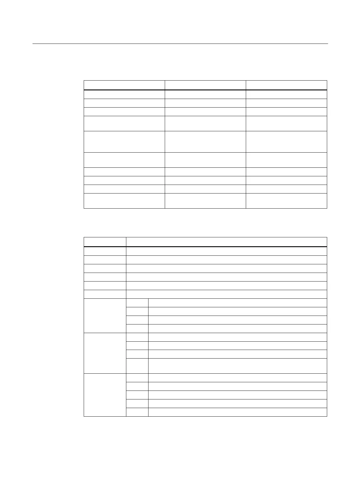
Structure of the sample application (OB1)
Call Conditions Subroutine Name Description
Each scan (SM0.0) AUX_MCP (SBR20) Auxiliary function
First scan (SM0.1) PLC_INI (SBR32) PLC initialization
Each scan (SM0.0) EMG_STOP (SBR33) Emergency Stop control
Each scan (SM0.0) MCP_NCK (SBR37) Transferring MCP and HMI
signals to the NCK interface
Each scan (SM0.0) HANDWHL (SBR39) Selecting a hand wheel through
the interface signal
DB1900.DBB1xxx
Each scan (SM0.0) AXIS_CTL (SBR40) Coordinate enabling control,
hardware limit, etc.
Each scan (SM0.0) SPINDLE (SBR42) Spindle control
Each scan (SM0.0) COOLING (SBR44) Cooling control
Each scan (SM0.0) TURRET1 (SBR46) HALL effect device turret control
Each scan (SM0.0) ServPlan (SBR48) Maintenance plan example: first
task
Setting relevant PLC machine data
Machine data Corresponding function
14510[12] JOG key layout
14510[20] The maximum number of tool positions
14510[21] Time for locking a turret (in 0.1s)
14510[22] The monitoring time for searching a tool (in 0.1s)
14510[24] Lubrication interval (in 1min)
14510[25] Lubrication duration (in 0.01s)
Bit 4 Control of X axis rotation monitoring
Bit 5 Control of Y axis rotation monitoring
Bit 6 Control of Z axis rotation monitoring
14512[16]
Bit 7 Handwheel assignment with the MCP / HMI
Bit 0 Turret function
Bit 1 Clamping function
Bit 2 Tailstock function
14512[17]
Bit 3 Selection between handwheel and hand-held unit (0: handwheel; 1: hand-
held unit)
Bit 2 One time automatic lubrication after the power-on
Bit 4 Stop signal for an external spindle
Bit 5 Fixing the direction of a spindle
Bit 6 Hardware limit is independent of the PLC application
14512[18]
Bit 7 One hardware limit triggered per axis (enabled when bit 6=0)
 Loading...


