Connecting
3.3 Connecting the interfaces on the PPU
Electrical Installation Manual
28 Operating Instructions, 12/2014, 6FC5397-2EP10-0BA0
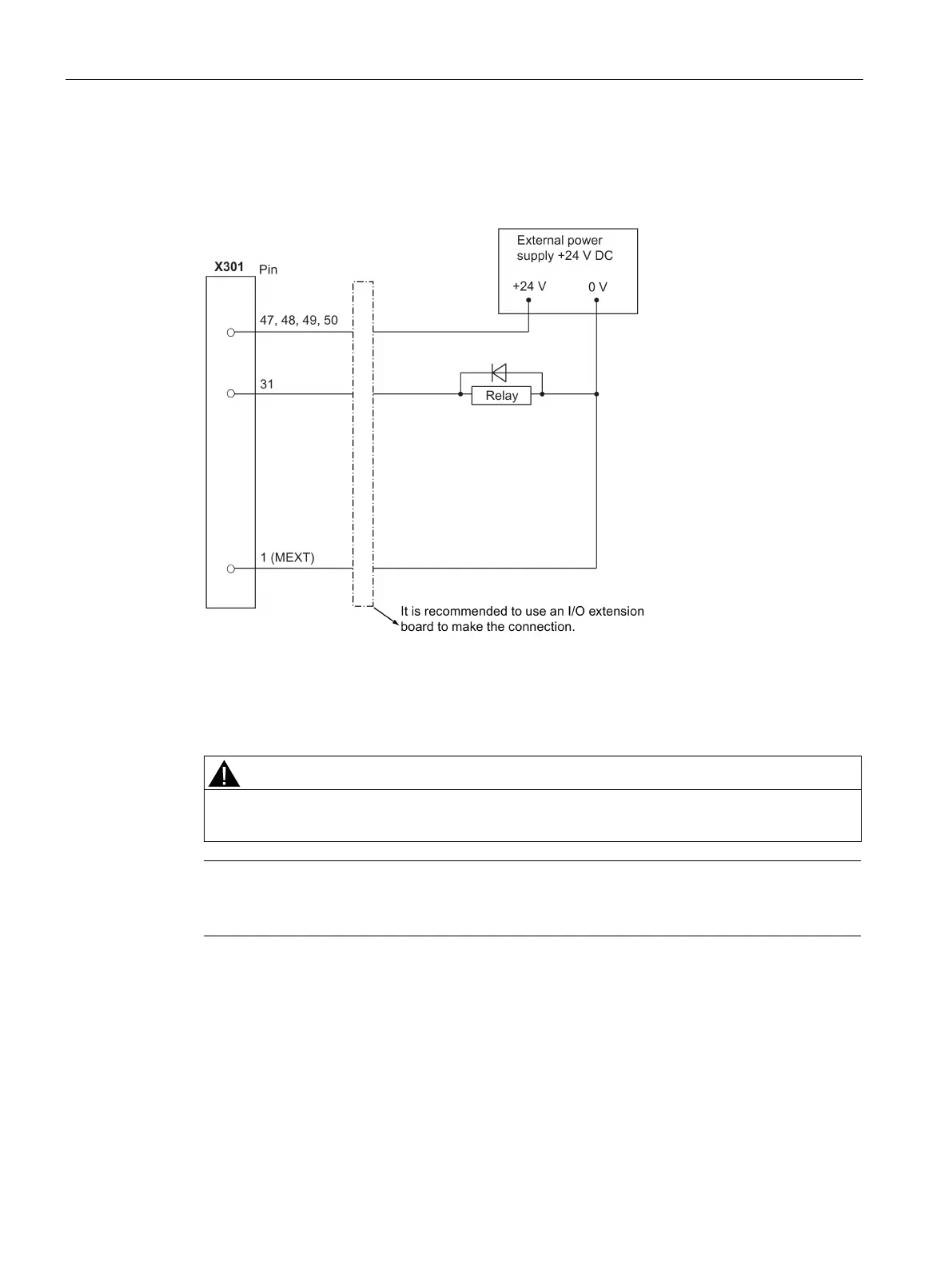
The diagram below shows you how to connect the connector pins of the digital outputs at
interface X301 (example). You can connect connector X302 in the same way.
To supply the digital outputs, you must connect an external 24 V DC power supply (X301,
X302: pins 47, 48, 49, 50).
You must also connect the reference ground of the external power supply to X301, X302: Pin
1 (MEXT).
You must ensure that the max. current consumption at pin 47, pin 48, pin 49, or pin 50 does
exceed 1 A.
You must connect the 24 V power supply for the digital outputs to
all the four power input
pins
(X301, X302:
).
When using an external power supply for the digital inputs, you must connect the reference
ground to X301, X302: Pin 1 (MEXT).