Connecting
3.3 Connecting the interfaces on the PPU
Electrical Installation Manual
Operating Instructions, 12/2014, 6FC5397-2EP10-0BA0
27
Be sure not to connect the pin 2 of X301/302 to ground; otherwise, the CNC controller or
the power supply could be damaged!
The 24 V output of X301/302 pin 2 comes from pins 47 to 50.
X301: IB3, IB4, IB5, QB2, QB3
X302: IB6, IB7, IB8, QB4, QB5
The connecting cable between the power source, load current supply connection, and
associated reference potential M must
exceed the maximum permissible length of 10 m.
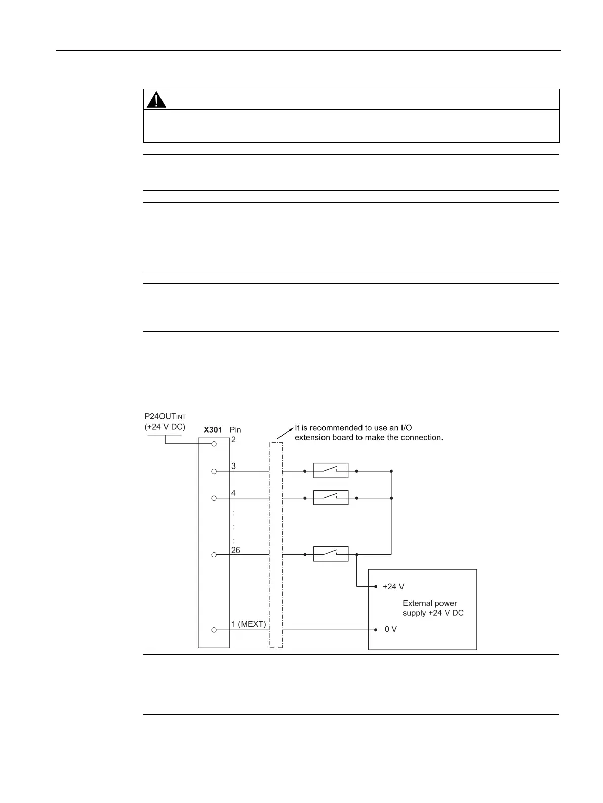
The diagram below shows you how to connect the connector pins of the digital inputs at
interface X301 (example). You can connect connector X302 in the same way.
When using an external power supply, you must connect the 24V (permissible range: 20.4 -
28.8 V) power supply for the digital outputs to
all the four power input pins
(X301, X302:
).