Data block for auxiliary systems
Up to 10 auxiliary systems are supported by the data block. A data structure is defined for each
auxiliary system. In order to display the energy/power of an auxiliary system in the HMI, bit 0
of the first byte of the data structure must be set.
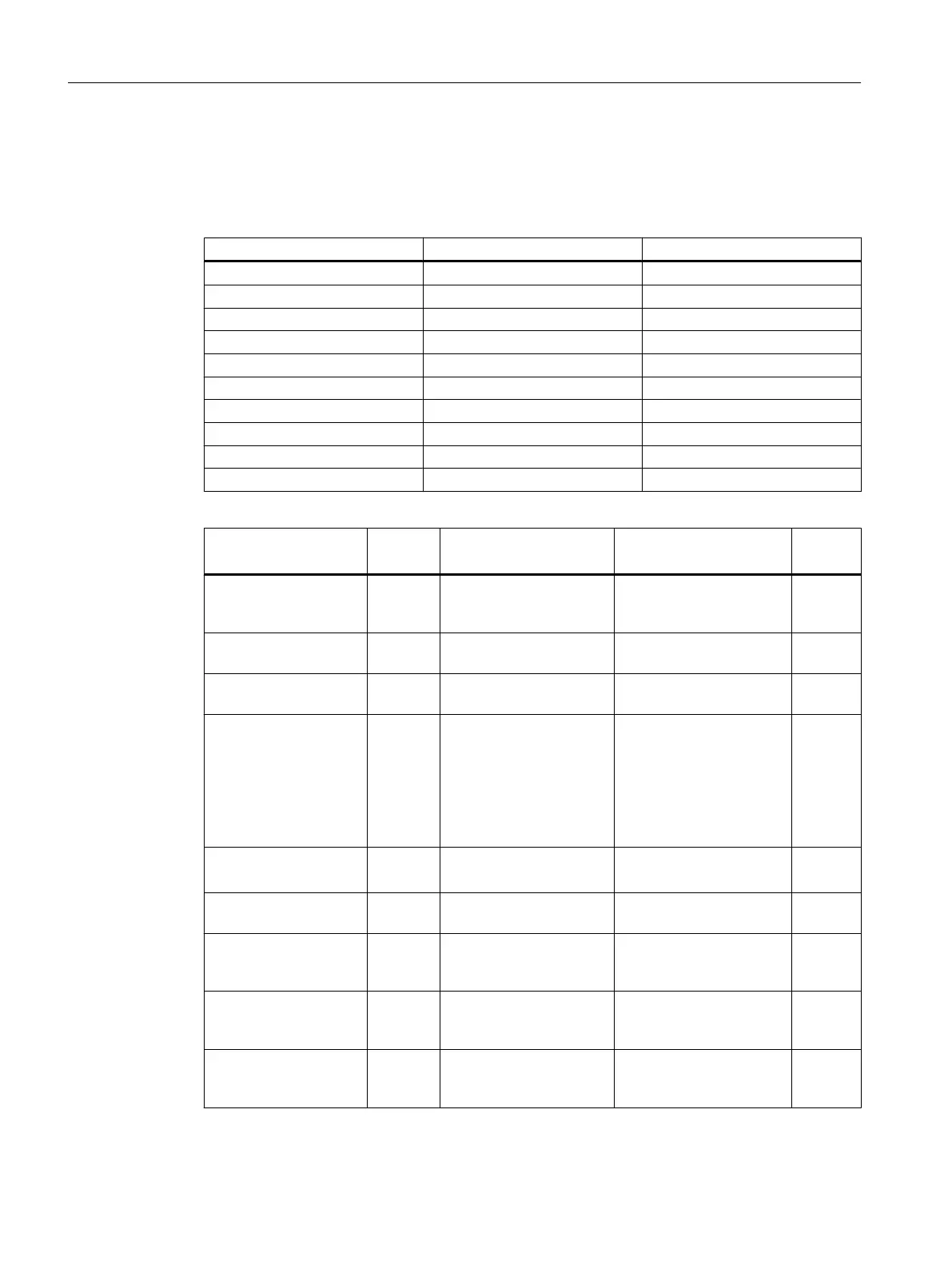
Auxiliary system Start of the data structure End of the data structure
Auxiliary system 1 (n=0) DB9907.DBB100 DB9907.DBB139
Auxiliary system 2 (n=40) DB9907.DBB140 DB9907.DBB179
Auxiliary system 3 (n=80) DB9907.DBB180 DB9907.DBB219
Auxiliary system 4 (n=120) DB9907.DBB220 DB9907.DBB259
Auxiliary system 5 (n=160) DB9907.DBB260 DB9907.DBB299
Auxiliary system 6 (n=200) DB9907.DBB300 DB9907.DBB339
Auxiliary system 7 (n=240) DB9907.DBB340 DB9907.DBB379
Auxiliary system 8 (n=280) DB9907.DBB380 DB9907.DBB419
Auxiliary system 9 (n=320) DB9907.DBB420 DB9907.DBB459
Auxiliary system 10 (n=360) DB9907.DBB460 DB9907.DBB499
DB9907
Name: SentronPac
Signal
direction
Meaning Identifier Format
DB9907.DBX(100+n).0 PLC ->
FW/HMI
FW calculates the energy/
power of the auxiliary sys‐
tem
ProcessAux BOOL
DB9907.DBX(100+n).1 PLC ->
FW/HMI
Actual value update ReadEnergy BOOL
DB9907.DBX(100+n).2 PLC ->
FW/HMI
Measurement in progress MeasACT BOOL
DB9907.DBX(100+n).3 PLC ->
FW/HMI
1: Differential values are
written to the variables for
the measurement end
0: Absolute values are
written to the variables for
the measurement start
and measurement end
MeasMode BOOL
DB9907.DBX(100+n).4 PLC ->
FW/HMI
1: Energy
0: Power
InputMode BOOL
DB9907.DBX(100+n).7 PLC ->
FW/HMI
Delete data structure ResetAux BOOL
DB9907.DBD(104+n) PLC ->
FW/HMI
Active power or active en‐
ergy of the auxiliary sys‐
tem
ActivePowerAux REAL
DB9907.DBD(108+n) FW ->
HMI
Active energy drawn by
the auxiliary system in
kWh
ActiveEnAux REAL
DB9907.DBD(112+n) FW ->
HMI
Active energy supplied by
the auxiliary system in
kWh
ReActiveEnAux REAL
Ctrl-E Analysis
3.3 Commissioning the PLC for Ctrl-E Analysis
Ctrl-Energy
32 System Manual, 01/2015, 6FC5397-0EP40-5BA2