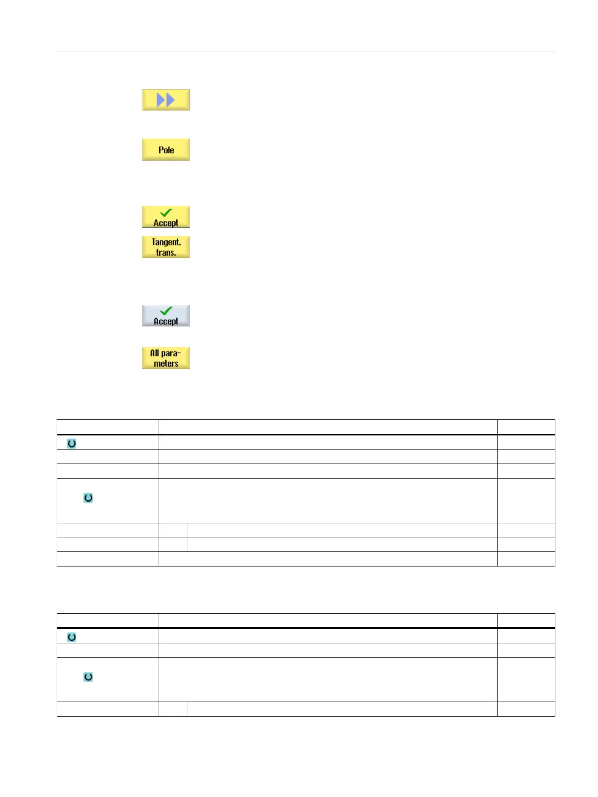
The "Pole Input" input window opens.
4. Enter all the data available from the workpiece drawing in the input screen
(e.g. length of straight line, target position, transition to next element,
angle of lead, etc.).
5. Press the "Accept" softkey.
The contour element is added to the contour.
6. When entering data for a contour element, you can program the transition
to the preceding element as a tangent.
Press the "Tangent to prec. elem." softkey. The "tangential" selection
appears in the parameter α2 entry field.
7. Repeat the procedure until the contour is complete.
8. Press the "Accept" softkey.
The programmed contour is transferred into the process plan (program
view).
9. If you want to display further parameters for certain contour elements,
e.g. to enter additional commands, press the "All parameters" softkey.
Contour element "Straight line, e.g. X"
Parameter Description Unit
X End point X (abs or inc) mm
α1 Starting angle e.g. to the X axis Degrees
α2 Angle to the preceding element Degrees
Transition to next ele‐
ment
Type of transition
● Radius
● Chamfer
Radius R Transition to following element - radius mm
Chamfer FS Transition to following element - chamfer mm
Additional commands Additional G code commands
Contour element "straight line, e.g. Y"
Parameter Description Unit
Y End point Y (abs or inc) mm
α1 Starting angle to X axis Degrees
Transition to next ele‐
ment
Type of transition
● Radius
● Chamfer
Radius R Transition to following element - radius mm
Programming technological functions (cycles)
10.3 Contour milling
Milling
Operating Manual, 08/2018, 6FC5398-7CP41-0BA0 487
 Loading...


