Description
9229 0025 176 0A 31
2019-08-05
Name plate
Technical data
Fig. 43 Technical data (excerpt from the catalogue)
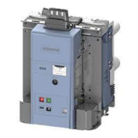
Dimensions and weights
The dimensions of the vacuum circuit-breaker can be taken from the relevant dimen-
sional drawing. If needed, they can be obtained from your Siemens representative.
The weight is indicated on the vacuum circuit-breaker name plate (see Fig. 42) or
refer to the associated dimension drawing.
Fig. 42 Example - name plate
1 Manufacturer
2 Year of manufacture
3 Rated normal current I
r
4 Rated short-circuit duration t
k
5 Weight m
6 Rated operating sequence
7 Classification as per standard
8 Rated power frequency withstand voltage U
d
9 Rated lightning impulse withstand
voltage U
p
10 Rated short-circuit breaking current I
sc
11 Rated voltage U
r
11 Rated frequency f
r
12 Factory number
13 Type designation
14 Quality control seal
Made in Germany
Q
600806
Kontr
0001-II-10_de
1
2
3
4
5
6
7
14
8/9
10
11
12
13
Type 3AE50123-2
No. S 3AE50123-2
Year of manufacture 2019
Rated operating sequence: O - 0.3 s - CO - 15 s - CO
Class as per IEC 62271-100: E2, C2, M2
Ur12 kV, fr 50/60 Hz
Isc 31.5 kA
Ud42kV, Up 95 kV
Ir 1250 A
tk3 s
m 80 kg
Rated voltage* U
r
kV 7.2 12 17.5 24
Rated normal current I
r
A 800 - 3150*** 2500
Rated lightning impulse withstand voltage (peak value)
U
p
kV 60 75 (95**) 95 125
Rated power frequency withstand voltage (effective
value) U
d
kV 20 (32**) 28 (42**) 38
50
(65**)
Rated short-circuit breaking current I
sc
kA 16 - 40 16 - 25
Pole-centre distance mm 150, 160, 210, 275 210, 275
Distance between lower and the upper terminal mm 205, 275, 310 310
Standard rated operating sequence O - 0.3 s - CO - 15 s - CO
* In the event of a rated frequency f
r
of 50/60 Hz
** On request
*** From 2000 A upwards only with 310 mm space between the lower and the upper terminal
and a pole-centre distance of 210/275 mm
 Loading...
