Installation
9229 0025 176 0A 55
2019-08-05
• Insert the handle of withdrawable part 3AX1430-2C into the coupling of the with-
drawable part.
• Turn inserted withdrawable part handle 3AX1430-2C clockwise in order to move
the vacuum circuit-breaker to a perceivable end stop.
Travel path lengths (optional):
- 180, 200 and 220 mm for all vacuum circuit-breakers up to 17.5 kV and
- 260 mm for all vacuum circuit-breakers with 24 kV.
Position queries during movement
If the low-voltage interface has been connected on the customer's premises, the fol-
lowing positions of the vacuum circuit-breaker with withdrawable part are sensed
during movement:
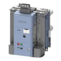
Fig. 91 Example - moving in the guide rails
Disconnected position/test position Intermediate position Entering position/service position
Switches –S1.5; –S1.6; –S1.7; –S1.8
send a signal or message
No signal Switches –S1.0; –S1.1; –S1.2; –S1.3
send a signal or message
For stabilisation purposes, a further locking bar is provid-
ed on the withdrawable part, which is automatically ex-
tended downwards by the handle of withdrawable part
3AX1430-2C during insertion.
For the size of the locking bar, refer to the dimension
drawing supplied.
Fig. 92 Locking bar on withdrawable part
 Loading...
