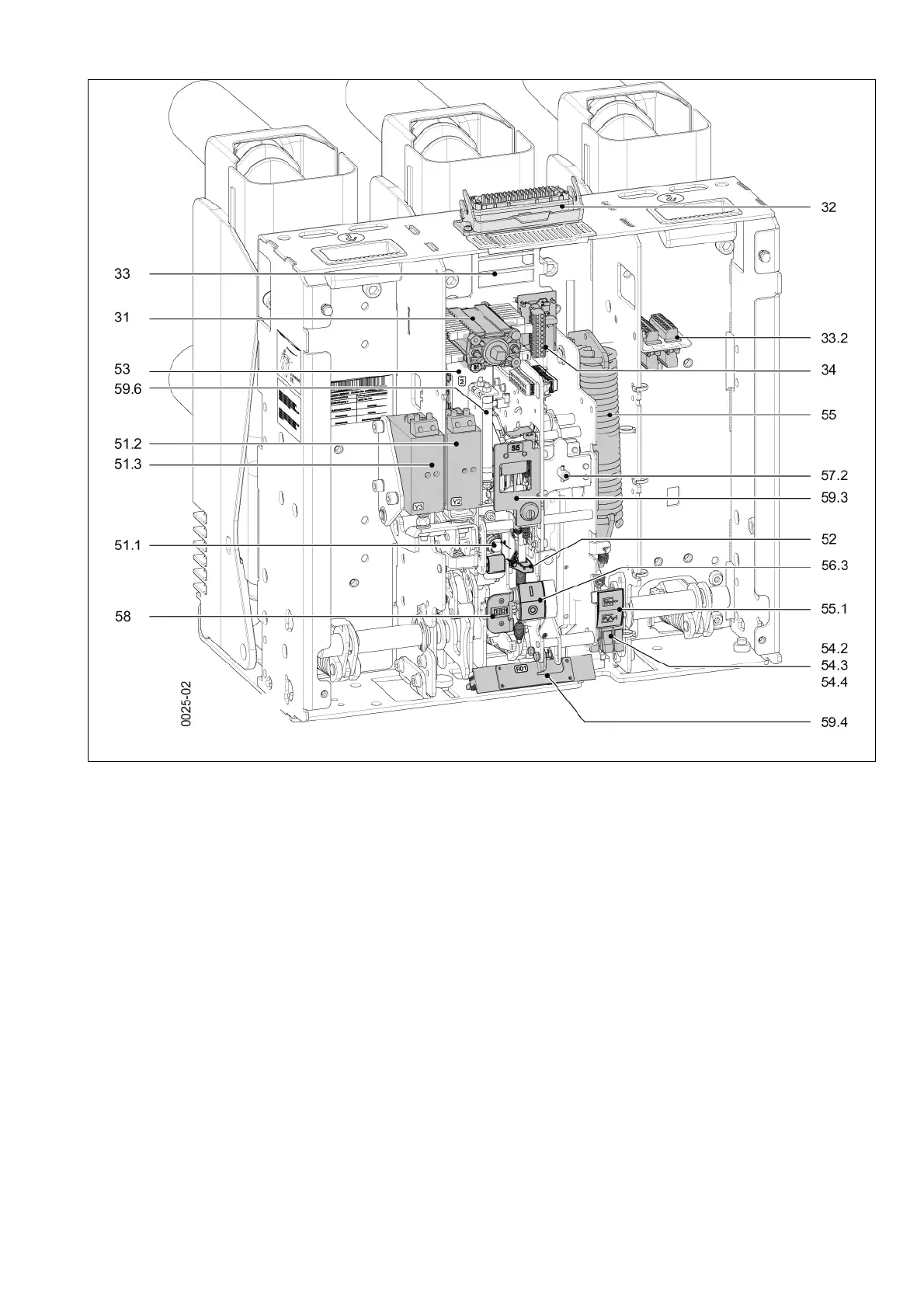
Fig. 18 Open operating mechanism, example 17.5 kV, 31.5 kA, 2500 A
31 Auxiliary switch (-S1)
32 Low-voltage plug connector (-X0) (optional)
33 Plug (Q0-X1.1, Q0-X1.2, Q0-X1.3) only when ordering the
20-pole or 30-pole connector strip (not shown)
33.2 Plugs (-X01) and (-X02) for withdrawable part (optional)
34 Anti-pumping device (-K1)
51.1 1st shunt release (-Y1)
51.2 2nd release (optional)
51.3 3rd release (optional)
52 Closing solenoid (-Y9)
53 Motor (-M1), charging the closing spring
54.1 Position switch (-S12), prevents electrical closing in
mechanical interlock (not shown)
54.2 Position switch (-S21), motor control
54.3 Position switch (-S3), control for (-K1) anti-pumping device
54.4 Position switch (-S4), signal “Closing spring charged”
54.6 Position switch (-S6), circuit-breaker tripping signal
(optional, not shown)
55 Closing spring
55.1 Spring state indicator
56.3 Position indicator CLOSED-OPEN
57.2 Hand crank coupling
58 Operations counter
59.3 Key-operated interlock (optional)
59.4 Heater (-R01), condensation water protection (optional)
59.5 Electrical closing lock-out (-Y8E) (optional, not shown)
59.6 Resistor (-R1), dependent on voltage 1 or 2 resistors, for
undervoltage release (-Y7) (optional)

 Loading...


