Manual
2 Installation
2.2 Electrical Connection
SIP ART DR24 6DR2410
C79000-G7476-C153-03
109
The SIPART DR24 is designed with a high electromagnetic compatibility (EMC) and has a
high resistance to HF interference. In order to maintain this high operational reliability we
recommend that all inductances (e.g. relays, contactors, motors) installed in the vicinity of or
connected to the controllers should be assembled with suitable suppressors (e.g. RC com-
binations)!
1Slot1
Main board
AE1 to AE3 (I/U)
AA1 to AA3
BE1 to BE4
BA1 to BA8 24 V
L+, M
2Slot2
AE4(I/U,R,P,T,V)
3Slot3
AE5(I/U,R,P,T,V)
4Slot4
Serial interface
5Slot5
4BA 24 V+2BE BA9 to BA12, BE5 to BE6
2BA relay BA9, BA 10
5BE BE5 to BE9
1AA AA7
3AE AE9 to AE11
3AA+3BA AA7 to AA9, BE5 to BE7
6Slot6
4BA 24 V+2BE BA13 to BA16, BE10 to BE11
2BA relay BA13, BA14
5BE BE10 to BE14
1AA(y-hold) AA4
3AE AE6 to AE8
3AA+3BE AA4 to AA6, BE10 to BE12
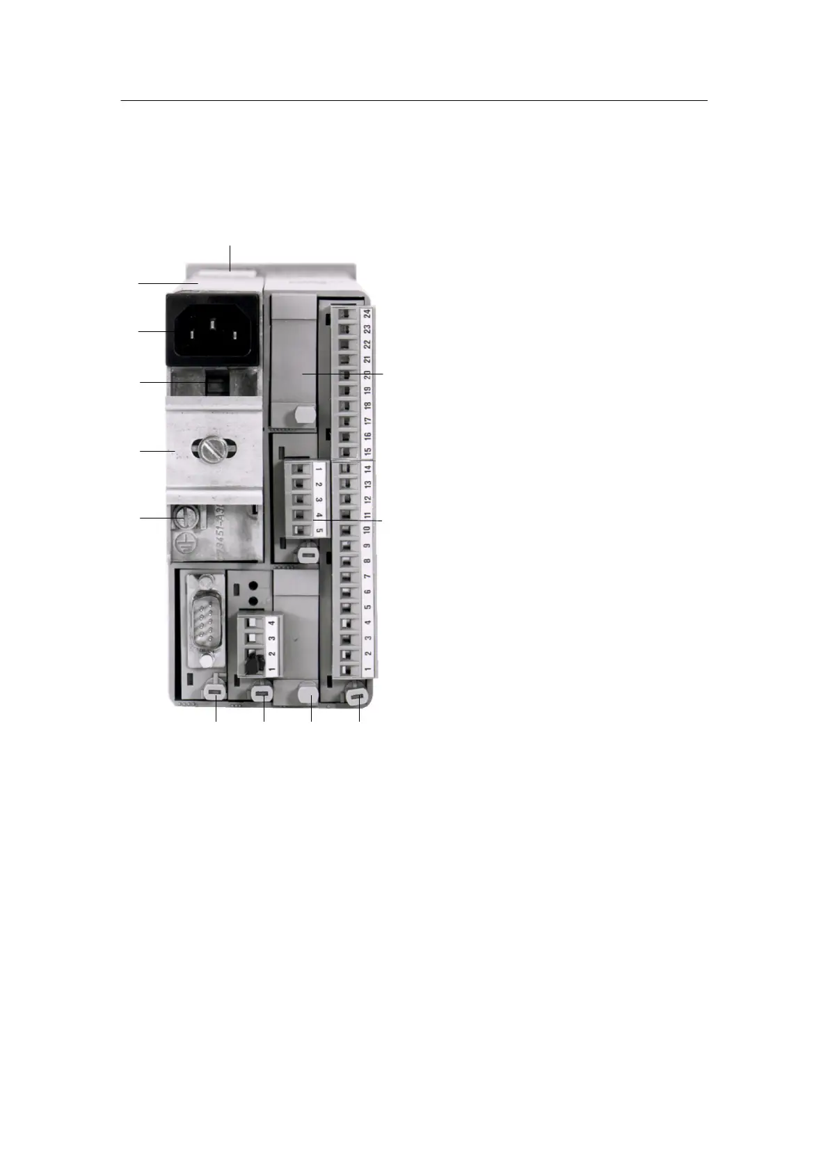
7 PE conductor contact s pring
8 Grounding screw
9 Mounting rail
(included in the scope of supply of
the 6DR2 804-8A/B relay modules)
10 Mains voltage selection s witch
11 Mains plug
12 Power supply unit
7
12
11
10
9
8
5
4 3 2 1
6
Figure 2-1 Rear panel
 Loading...


