2 Installation
2.2 Electrical Connection
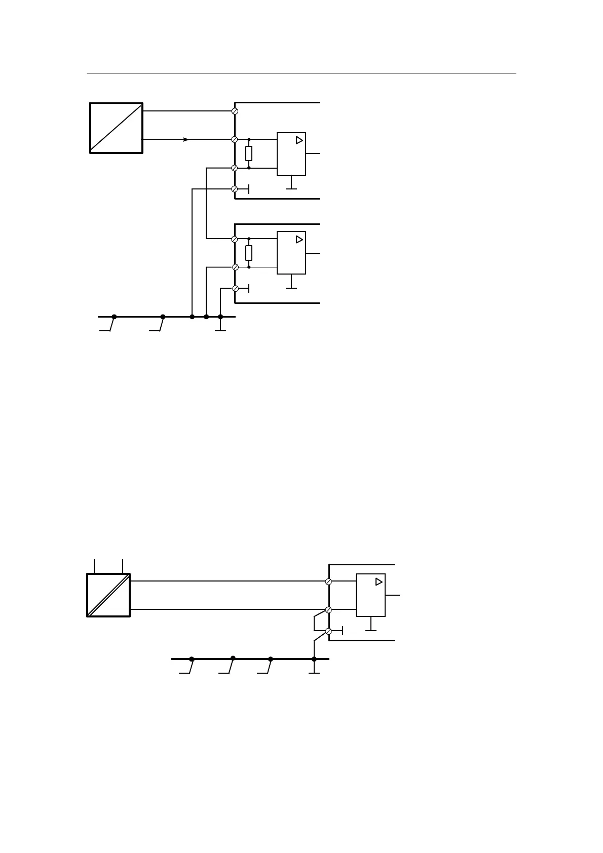
2.2.4 Alternative Wiring for I- and U Input
Manual
126
SIP ART DR24 6DR2410
C79000-G7476-C153-03
I
4to20mA
49.9 Ω
+
49.9 Ω
+
instrument 1
instrument 2
+
L+
AE+
AE--
GND
AE+
AE--
GND
--
--
--
Figure 2-33 Connection of a 2-wire transmitter 4 to 20 mA to two instruments in series and supplied by L+
from one of the instruments
Every input amplifier is supplied by a differential voltage of 0.2 to 1 V. Instrument 1 also has a
0.2 to 1 V common--mode voltage that is suppressed in this case. Several instruments with a
total common--mode voltage of up to 10 V can be connected in series. As the last instrument’s
input is connected to ground, its input impedance is referred to ground.
As there will be an increased impedance (maximum permissible common--mode voltage +10 V),
the permissible impedance voltage of the transmitter or the on--load voltage may not be ex-
ceeded!
D Voltages 0/0.2 to 1 V or 0/2 to 10 V
U
--
U
H
+
--
+
AE+
AE--
GND
Figure 2-34 Wiring of a floating voltage supply

 Loading...


