Manual
3 Operation
3.3 Configuring Mode (Parameterization and Configuring Mode)
3.3.5 Configuring Mode hdEF (Define Hardware)
SIP ART DR24 6DR2410
C79000-G7476-C153-03
151
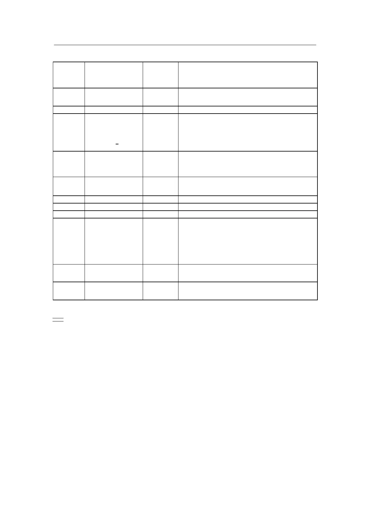
Question
dd2
Hardware
function
Answer
dd1
Hardware selection
Factory
setting
Meaning
AA1
↓
AA9
0MAor4MA 0MA
Signal range analog outputs 0 mA/4 mA
AAU no or YES no
Analog output switching
AE1
↓
AE3
no, 0 MA or 4 MA no
Signal range analog outputs 0 mA/4 mA
AE4, AE5 no,0MA,4MA
Uni._
Uni.
_
no
Signal range analog inputs 0 mA/4 mA
Uni--module: 0 at sensor failure
Uni--module: 1 at sensor failure
AE6
↓
AE11
no, 0 MA or 4 MA no
Signal range analog inputs 0 mA/4 mA
AEFr 50 H or 60 H 50 H
Analog inputs mains frequency suppression
bAtt
bAU
no or YES
no or YES
YES
no
Battery backup RAM (restart conditions)
switchover of digital output
dA--L dA2 or L14 dA2
Display selection analog display or LED
dPon no or YES no
Flashing of dd1 to dd3 at Power on
nAME o1) to 254 0
Name (ID) of user program memory
oP5
↓
oP6
no
4bA
5bE
2rEL
1AA
3AE
3AA
no
Options in slot 5/6
none
4BA24V/2BE
5BE
2BA Relay
1AA y-hold
3AE
3AA/3BE
SES no or YES
no = read only
YES = read and write
YES
Serial interface
tA1.U
↓
tA7.U
no, YES or Four no
Key switching
1)
Position 0 cannot be set manually. As soon as the factory setting is changed (parameter or
configurin g ), naME is automatically set to 1. APst sets naME to 0.
High speed steps
Table 3-6 Hardware function list in the configuring mode hdEF
 Loading...


