5 Maintenance
5.1 General Information and Handling
Manual
172
SIP ART DR24 6DR2410
C79000-G7476-C153-03
D Replacing the power supply unit
- Pull out the mains plug!
- Loosen the clamps and remove the device from the panel.
- Loosen the four fixing screws of the power supply unit (see (2) Figure 5-3) (not the 3
plated Phillips screws (3) Figure 5-3) and pull out the power supply unit in screw direc-
tion.
- Bend the PE conductor contact spring slightly upwards and place the new power supply
unit carefully on the plug terminals in screw direction and make sure the guide lugs snap
in by moving slightly from side to side (it can no longer be moved from side to side when
it has snapped in).
- Tighten the four fixing screws diagonally.
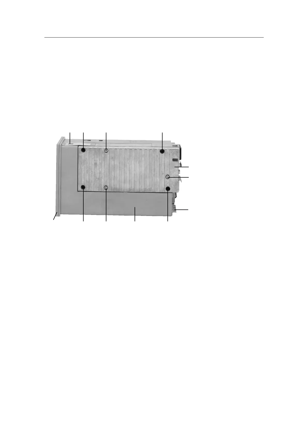
1 PE conductor contact spring
2 Fixing screws for the power supply unit
3 Plated Phillips screws for
fixing the power supply circuit board in the housing
4 Power supply unit
5 Blanking plate
6 Plastic housing
7 Front module
1 2 3 2
32
7
26
3
5
4
Figure 5-3 Fixing the power supply unit
D LED test and software state, cycle time
If the Shift key (tA5) is pressed for about 10s (after 5 s “PS” appears flashing on dd3), this
starts the LED test. All LEDs turn on, the digital displays show “18.8.8.8” or “
.
8.8.8.” and a
light spot from 0 to 100 % consisting of three LEDs runs on the two analog displays (on
reaching 100 % the light spot starts again at 0 %).
If tA1 is also pressed permanently during the lamp test, “dr24” appears on dd1 and the soft-
ware state of the device appears on dd2 and the cycle time in ms on dd3.
During the LED test and display of the software state and cycle time, t he SIPART DR24 con-
tinues to operate online in its last operating mode.

 Loading...


