Manual
7 User Examples
7.4 T wo-position Controller for Heating and Cooling (Example 4)
SIP ART DR24 6DR2410
C79000-G7476-C153-03
189
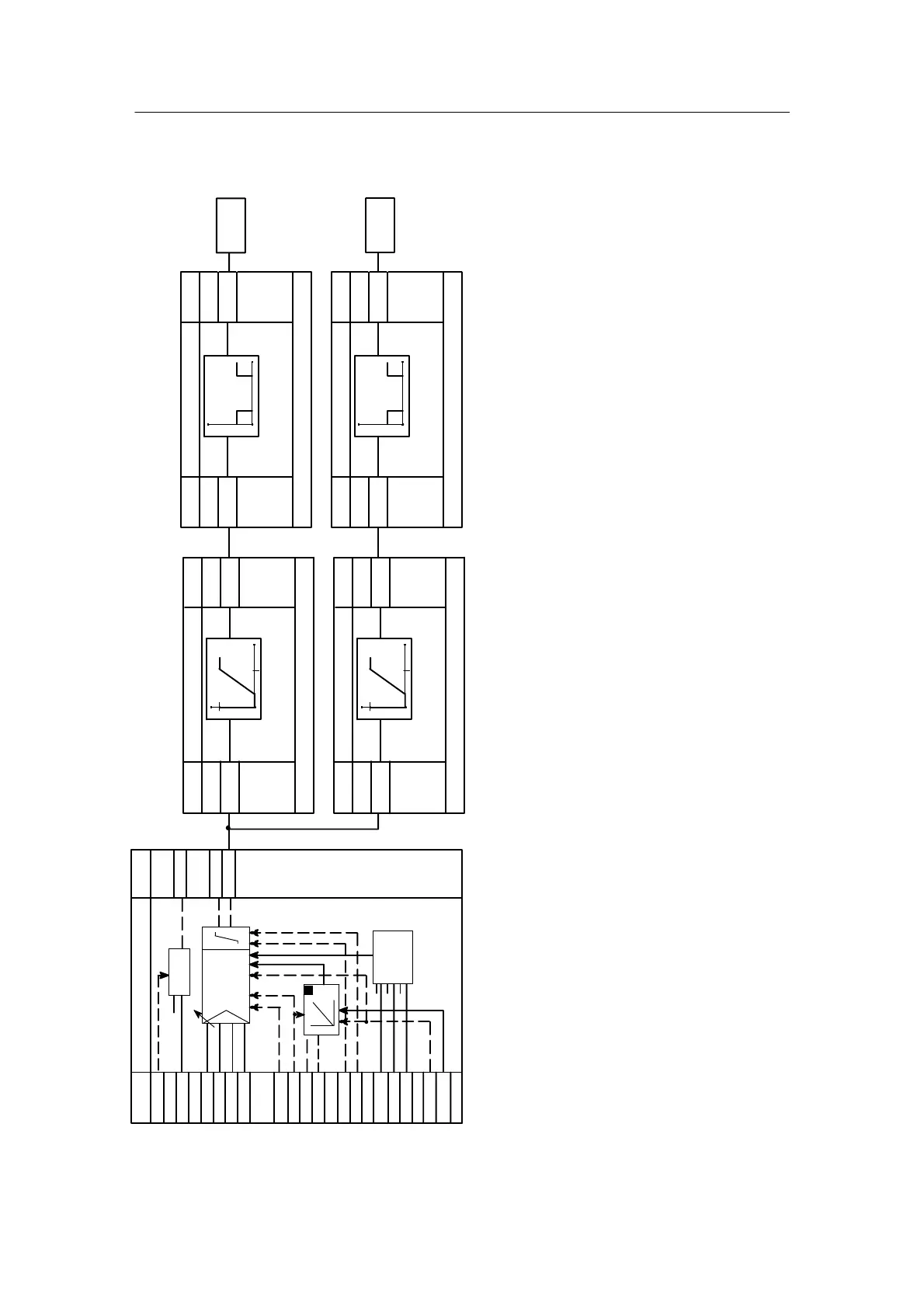
D Wiring diagram (example 4, supplement to the wiring diagram of example 3)
#bA1.1
Heating
#bA2.1
Cooling
Two--position controller
The switching output can also supply continuous con-
tact through y
a
= -1 % and y
e
= 101 % of the PID
controller . The control loop is optimized with k
p
,T
n
,
T
v
.
The controller is adapted to the different line amplifi-
cation of the heating and cooling channel with the
parameters SPA, SPE.
The controller is adapted to the final control elements
with the parameters tAE, tM.
See example 3 for complete K-controller.
Ccn1
h01.F
cP
tn
tV
# .01
∩ .02
∩ .03
∩ .04
∩ .05
∩ .06
# .07
# .08
# .09
# .10
# .11
# .12
∩ .13
∩ .14
∩ .15
# .16
∩ .17
.1A#
.2A∩
.3A∩
Av
Adaptation
Yz
XdP
XdD
xdI
K-controller
kp,Tn,Tv,AH,YA,YE
x
Y
P
H
+Δy
-Δy
AL
+yBL
--y BL
SG1
SG2
SG3
Ya
Y
tY
N
Parameter
control
N
Yn
E
A
.A∩
c02.F
∩ .1
n
---
(onPA)SPA, SPE
SPr1
A
E
.A
c04.F
∩ .1
n
---
PUM1
(onPA)tAE, tM
E
A
.A∩
c03.F
∩ .1
n
---
(onPA)SPA, SPE
SPr2
A
E
.A
c05.F
∩ .1
n
---
PUM2
(onPA)tAE, tM
A
t
A
t
E
E
n003

 Loading...


