1 Technical Description
1.5 Functional Description
1.5.1 Basic Structure
Manual
22
SIP ART DR24 6DR2410
C79000-G7476-C153-03
The connectable parameters and most private parameters can be set during operation in the
parameterization mode (online parameters). The other part of the private parameters is set of-
fline in the configuring mode oFPA and CLPA.
The parameter and configuration data are stored in a non-volatile plug-in user program memory
with an EEPRO M .
The cycle time in online operation depends on the scope of the user program and is a minimum
60 ms. About 2 ms are necessary on average per basic function, and about 5 ms per complex
function. The cycle time in offline operation is 100 ms.
Addition of the individual times gives the total cycle time t
c
which changes in 10 ms steps.
The current cycle time can be displayed during the lamp test (see chapter 5.1, page 169) by
additionally pressing tA1. dd3 shows the cycle time in ms.
On average you can reckon on 80 to 120 ms cycle time.
32 basic functions
can be used in 109 arithme-
tic blocks
b**.F
59 complex functions with
private parameters can be
used in blocks
c**.F
d0*.F
h0*.F
with varying frequency
Connectable parameters
Constants
Fault messages
Operating modes: Process operation
Parameterization (Online)
AdAP Adaptation
Configuring (Offline)
oFPA Offline parameters
CAE4 Parameterize UNI-module for AE4
CAE5 Parameterize UNI-module for AE5
CLPA Clock parameters
hdEF Define hardware
FdEF Define functions
FCon Wire functions
FPoS Position functions
APSt Load factory setting (all preset)
Read SES
Analog outputs
SAA1...16
Digital outputs
Sb(A)1...16
User program memory
Analog inputs
AE1...11
Digital inputs
bE1...14
Write SES
Analog inputs
SA(E)1...16
Digital inputs
Sb(E)1...16
Analog outputs
AA1...9
Digital outputs
bA1...16
Displays dA1, dA2,
dd1 to dd3
LEDs
L01...13
Keys
ta1...7
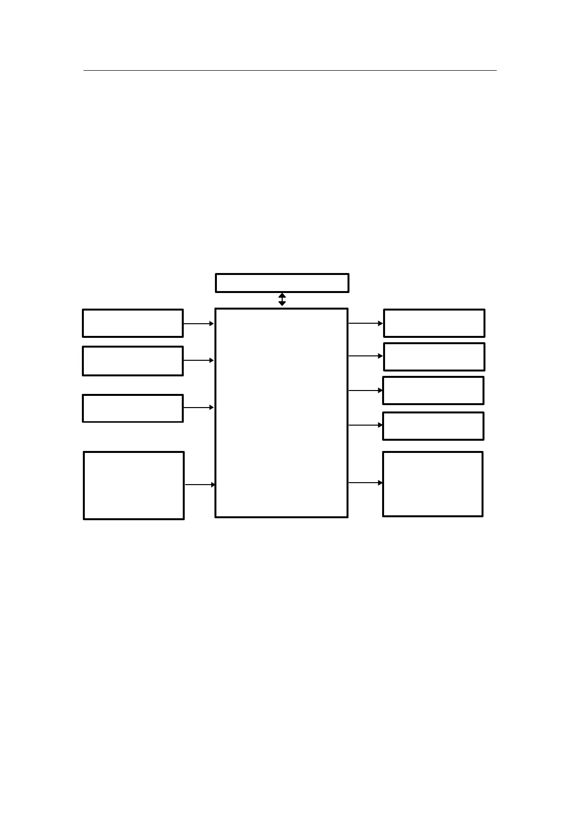
Figure 1--5 Block diagram of the SIPART DR24
 Loading...


