1 Technical Description
1.5 Functional Description
1.5.7 Basic Functions (Arithmetic blocks b)
Manual
48
SIP ART DR24 6DR2410
C79000-G7476-C153-03
Counter
Every positive edge at E2 (m) counts A 0.001 upwards
when E1 = low. Every positive edge at E3 (Reset) sets
A to 0.000. The counting range goes up to 50000 ⋅0.001
= 50; other counting pulses are not evaluated. If the out-
put of the counter is switched with the d isp lays dd1 o r dd2
(dA = 0, dE = 1000, dP =
)a maximum of 10000
counting pulses can be displayed, then oFL appears.
Only one counting pulse per 2 computing cycles can be
evaluated. If a control signal is to be output dependent
on the counter reading, the basic function Comparator
(CoMP) must be connected with the counter and the
counter reading compared with an adjustable parameter
(PL**) (see figure 1--19 and 1--20, page 48).
E1 E2 (m) E3 (R) A Remarks
x x ↑ CT = 0.000 Reset
1x1/0 CTo
1)
0 ↑ 1/0 CT+n⋅m Counting pro-
cess
1)
Counter reading saved, count input blocked
Example:
1375 = 1.375/0.001 pulses are
to be counted from the start.
The counter reading is shown
on one display and is retained
until a new start command.
t
Counter
reading
t
Start
b01.3
t
PL11
= 1.375
b01.A
b02.A
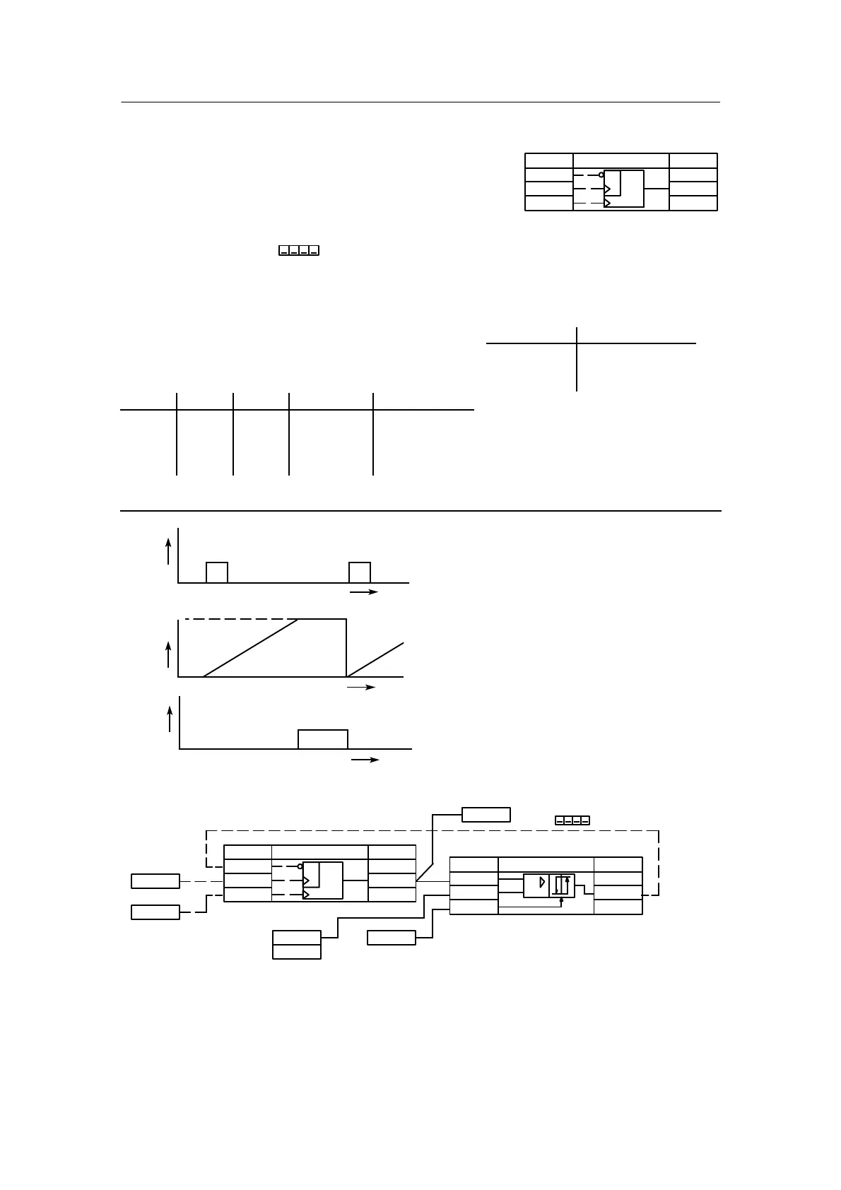
Figure 1--19 Dependence of the output signals on the input signals at the counter
Counting pulses
Start
dA = 0
dE = 1000
dP =
H
b02.A#
∩b02.F
∩b02.1
∩b02.2
∩b02.3
n002
CoMP
+
-
+m
CT
m
R
&
b01.A∩
b01.F
#b01.1
#b01.2
#b01.3
n001
CoUn
0.000
∩PL11∩
1.375
bE2
#
tA1.1#
∩
dd1.1
Figure 1--20 Connection of a counter with a comparator; at the specified numeric value 1.375
(corresponds to 1375 metering pulses) a high signal is output by CoMP
Restart conditions:
Power on output A
bAtt = no 0.000
bAtt = YES last value
(hdEF)
+m
CT
ncon
Lo
Lo
m
R
&
.A∩
b.F
--
# .1
# .2
# .3
n
---
CoUn
 Loading...


