1 Technical Description
1.5 Functional Description
1.5.8 Complex Functions (Arithmetic blocks c, d, h)
Manual
54
SIP ART DR24 6DR2410
C79000-G7476-C153-03
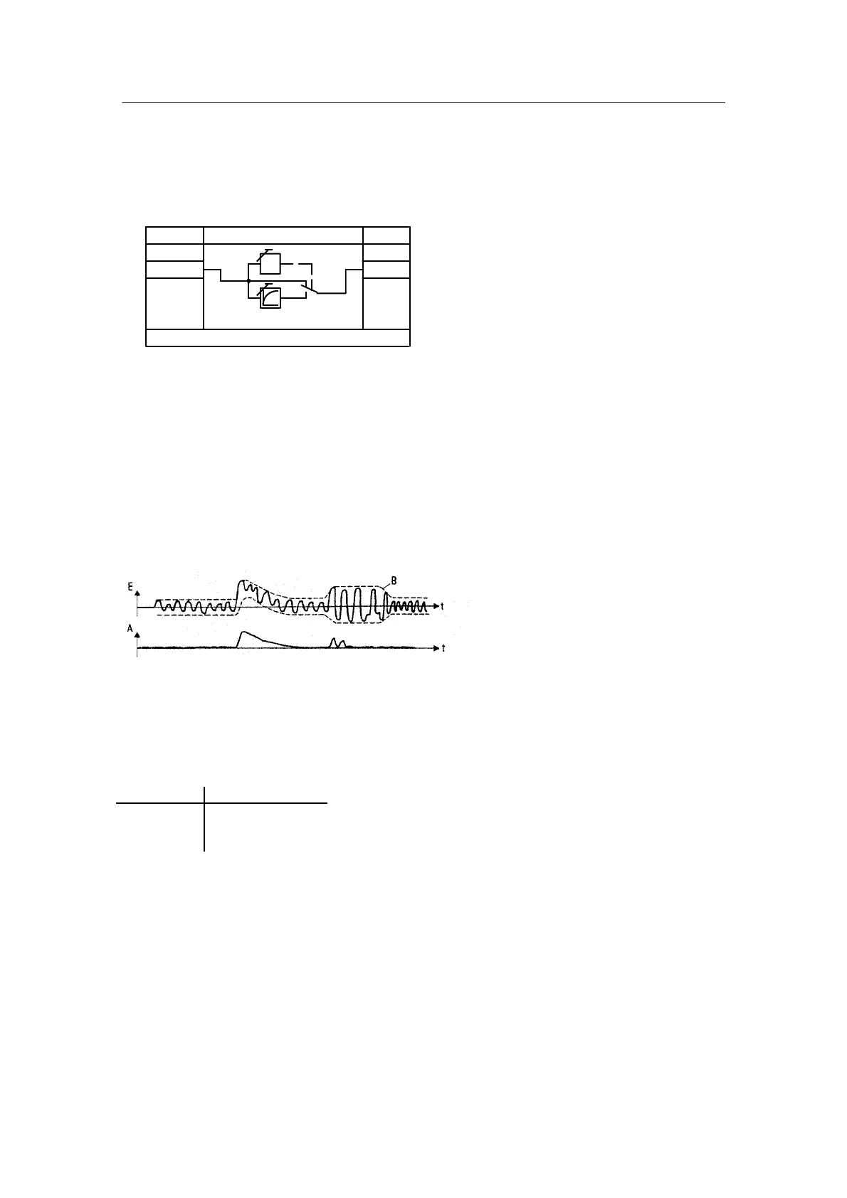
Adaptive filter AFi1, AFi2
Fault at E smaller than B : A = E(1 -- e
-t
)
Fault at E greater than B: A = E
<B
>B
E
Autom.
tF
A
ncon
t
B
.A∩
c.F
--
∩ .1
n
---
AFi1, AFi2
(onPA)tF
Within a band B in which periodic fault signals occur, these changes at input E (c**.1) are con-
sidered as faults by the filter and filtered with the set time constant tF. Changes in a direction
leading out of the filter band are passed unfiltered to the output A (c**.A) in order to allow fast
signal change in a controlled system for example. If the fault level changes in the meantime, the
band automatically adapts itself to the new level (Figure 1--22).
Because the filter band sets itself automatically and B is therefore not known, the time constant
tF may only be selected so great that the control loop would not oscillate even at a great filter
band for control technical reasons: tF < T G (T g = delay time of the control system). When
using the D part (PD, PID) use of the adaptive non--linear filter is highly recommended because
the input noise amplified by Kp ⋅ vv can be suppressed.
Figure 1--22 Effect of the adaptive non--linear filter
Restart conditions:
Power on Output A
bAtt = no 0.000
bAtt = YES last value
(hdEF)
 Loading...


