Manual
1 Technical Description
1.5 Functional Description
1.5.8 Complex Functions (Arithmetic blocks c, d, h)
SIP ART DR24 6DR2410
C79000-G7476-C153-03
71
- CLTi time interval setting
The intervals assigned to the programs in CLPr initially have factory setting (minimum
time 00.01). The times are entered as Δt according to the set clock format in h/min or
min/s.
This means: 01.n 1st interval of the program n
02.n 2nd interval of the program n
with n = 1 to 8 and the max. possible interval number 1 to 40 over all programs
If d*.3A (interval display) is wired with dd3, the appropriate intervals are didplayed in on-
line mode.
Corrections:
T ime corrections are made by changing the times in CLti.
- CLA1, 2 analog output function(amplitude default)
T wo independent output functions can be assigned to the common time base with CLA1
and CLA2. The functions are composed of linear sections. In the 1st interval of the re-
spective program n, the input of the start value for t = 0 (00.n) and the end value (01.n)
for the 1st linear section of the program n is necessary. In the other intervals only the end
values are entered for the sections of the polygon line. The end values are at the same
time start values for the next interval. If an interval is occupied by noP (no operation), the
analog value is calculated as an intermediate value of the adjacent vertexes in this inter-
val. If the 1st value 00.n is occupied by noP, no analog output CLA1, 2 is possible for this
program, 0 % is output.
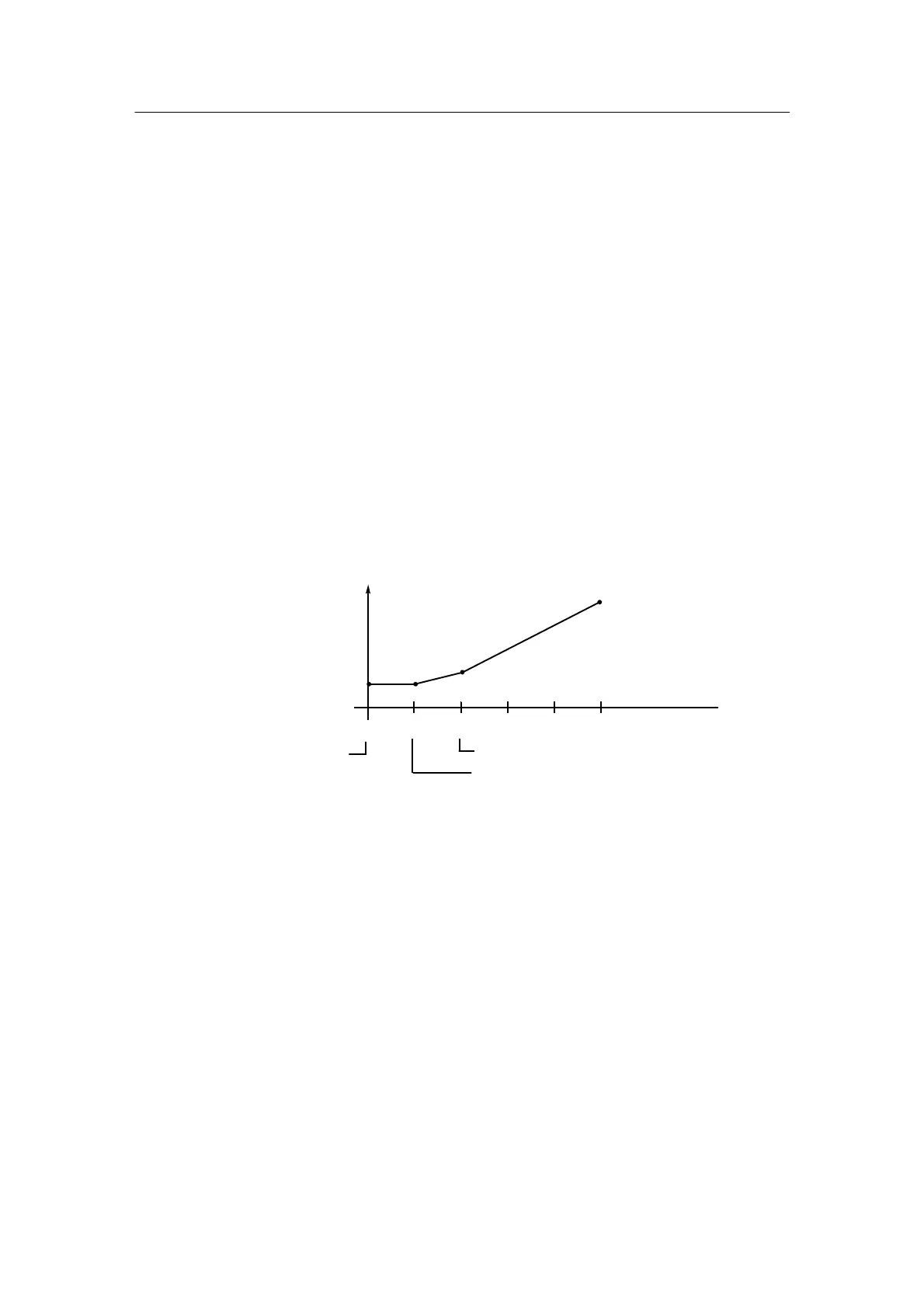
01.1 02.1 03.1 Vertexes05.100.1 04.1
123 54 Interval no.
Interval 3 and 4
defined with noP
Analog value corrections:
By overwriting
Start (t = 0) 1st interval
End 2nd interval = start 3rd interval
End 1st interval = start 2nd interval
- CLb1 to CLb8 digital status in the interval
Eight independent digital outputs CLb1 to CLb8 can be assigned to the common time
base.
The status, Low or High, is entered in the displayed interval.
Status corrections:
By overwriting
- Configuring
The clock is at a standstill during configuring. It must be restarted according to the start
condition from the start of the program after exiting the mode CLPA, hdEF, FdEF, FCon
and FPoS when changes are made in the configuring. Without changes, the clock contin-
ues running from the interrupt when entering OnPA or the process operation mode.
The clock continues running during the parameterization mode.
- Power failure
The clock stops running in the event of a power failure!
 Loading...


