Do you have a question about the Siemens SIPLUS CMS4000 and is the answer not in the manual?
| Brand | Siemens |
|---|---|
| Model | SIPLUS CMS4000 |
| Category | Cables and connectors |
| Language | English |
Indicates an imminently hazardous situation resulting in death or serious injury.
Indicates a potentially hazardous situation resulting in death or serious injury.
Indicates a potentially hazardous situation resulting in minor or moderate injury or property damage.
Indicates a potential situation resulting in an undesirable result or state.
Defines personnel authorized to install and work on equipment.
Specifies the approved applications and connection requirements for the device.
Lists registered trademarks and intellectual property rights.
States limitations of liability regarding document accuracy and product deviations.
Explains how the operating instructions support the use of the IFN AI-D.
States the necessity of basic automation technology and condition monitoring knowledge.
Confirms the document is valid for the Interface Node IFN AI-D.
States that there are no modifications compared to the previous version.
Confirms the IFN AI-D meets EG-Guideline requirements for electromagnetic compatibility.
Directs users to chapter 6.1 for detailed information on standards.
Advises to use additional instructions for SIPLUS CM X-Tools.
States the IFN AI-D is recyclable and advises on disposal methods.
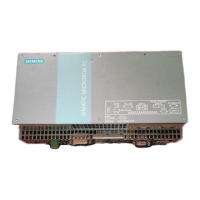
Defines SIPLUS CMS as a modular, scalable condition monitoring system for industrial plants.
Lists suitability for industrial environments, compact design, and ease of handling.
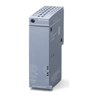
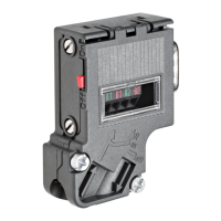
Details the IFN AI-D's display elements, including LEDs and connectors.
Lists the items included in the package: Device IFN AI-D and Operating Instructions.
Provides instructions for checking the package for completeness and transport damages.
Describes suitability for DIN Rail or mounting angles and provides dimensions.
Explains how to hang the device on the DIN rail and snap it in.
Details steps to remove the device from the DIN rail after disconnecting cables.
Explains connecting mounting angles to the device and installing it.
Details steps to demount the device from its installation site.
Provides step-by-step instructions for replacing the label plate.
Covers DC 24V supply, protection against electrical influences, and grounding.
Explains how to connect the device to ground using a 2.5mm² cable and M4 ring eye.
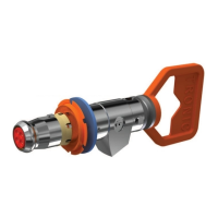
Details the procedure for connecting M12 connectors by pushing and twisting.
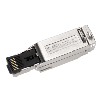
Explains connecting the M12 connector for IEEE1394 communication and pin assignment.
Details connecting the 5-pin M12 connector for power supply and Y-connector usage.
Explains connecting sensors to the 5-pin M12 analog input connectors and shielding.
Outlines software requirements and steps for commissioning and start-up.
Describes the meaning of different LED indicators (PWR, ERR, LNK, CH1-6) for diagnosis.
Refers to the SIPLUS CMS X-Tools Reference Manual for detailed diagnosis information.
Provides guidance for mixed configurations with ION and IFN devices on a bus line.
Lists EMC directive requirements, industry standards, and conformity certificates.
Details communication specifications including connectors, data protocol, and transfer rate.
Provides technical specifications for the power supply connection, including voltage, current, and protection.
Lists detailed specifications for analog inputs, including voltage, current, resistance, frequency, sampling rate, and accuracy.
Displays exemplary filter characteristic curves for analog input channels.
Details specifications for functional earth connection, including cable, resistance, and capacitance.
Lists environmental parameters like temperature, humidity, and atmospheric pressure.
Lists product order numbers (MLFB) for the device, accessories, and cables.
Defines abbreviations used throughout the document, such as AI, IFN, CMS, TIA.