Modbus register map
7SJ61/62/63 6MD63 - Modbus
C53000-L1840-C001-01
6-3
6.3 Coil status registers (0X references)
The coil status register block allows the Modbus master:
• command outputs through the output relays of the SIPROTEC
device (external commands),
• manipulation of taggings (internal commands), which can be
changed by Modbus,
• reading the checkback indication and/or the status of output relays
as well as taggings.
Note
The allocation of the output relays to the switching devices and to the
output channels is defined during parametrization of the SIPROTEC
devices.
Depending on the device composition there may be less than indicated
output relays (and corresponding Modbus registers) available in the
SIPROTEC device.
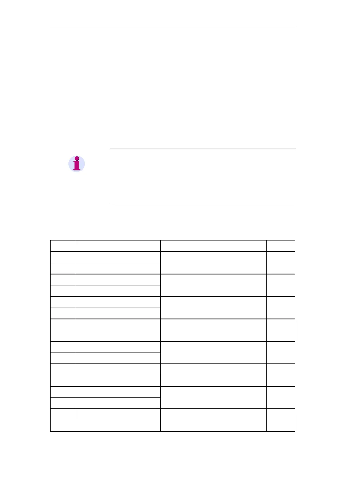
6.3.1 Register addresses 00001 to 00018: Double commands
•
Data type definition ref. to chap. 5.2.
Register
address
Designation of the
SIPROTEC objects
Comments
Internal
object no.
00001 Q0 ON/OFF
ON
00002 Q0 ON/OFF
OFF
Impulse output,
3 relays (2-pole ON, 1-pole OFF)
–
00003 Q1 ON/OFF
ON
00004 Q1 ON/OFF
OFF
Impulse output,
2 relays, 1-pole
–
00005 Q8 ON/OFF
ON
00006 Q8 ON/OFF
OFF
Impulse output,
2 relays, 1-pole
–
00007 Q2 ON/OFF
ON
00008 Q2 ON/OFF
OFF
Impulse output,
2 relays, 1-pole
–
00009 Q9 ON/OFF
ON
00010 Q9 ON/OFF
OFF
Impulse output,
2 relays, 1-pole
–
00011 Switching device D1 (UsrDC1)
ON
00012 Switching device D1 (UsrDC1)
OFF
Impulse output,
4 relays (2-pole)
–
00013 Switching device D2 (UsrDC2)
ON
00014 Switching device D2 (UsrDC2)
OFF
Impulse output,
2 relays, 1-pole
–
00015 Switching device D3 (UsrDC3)
ON
00016 Switching device D3 (UsrDC3)
OFF
Impulse output,
2 relays, 1-pole
–
 Loading...