Getting Started
36
7SS52 V4 Manual
C53000-G1176-C182-3
Bay unit 7SS525
To change the rated control voltages of the binary inputs in a bay unit:
Open the front panel. The location of the EFE_10 module is shown in Figure 2-5,
page 20.
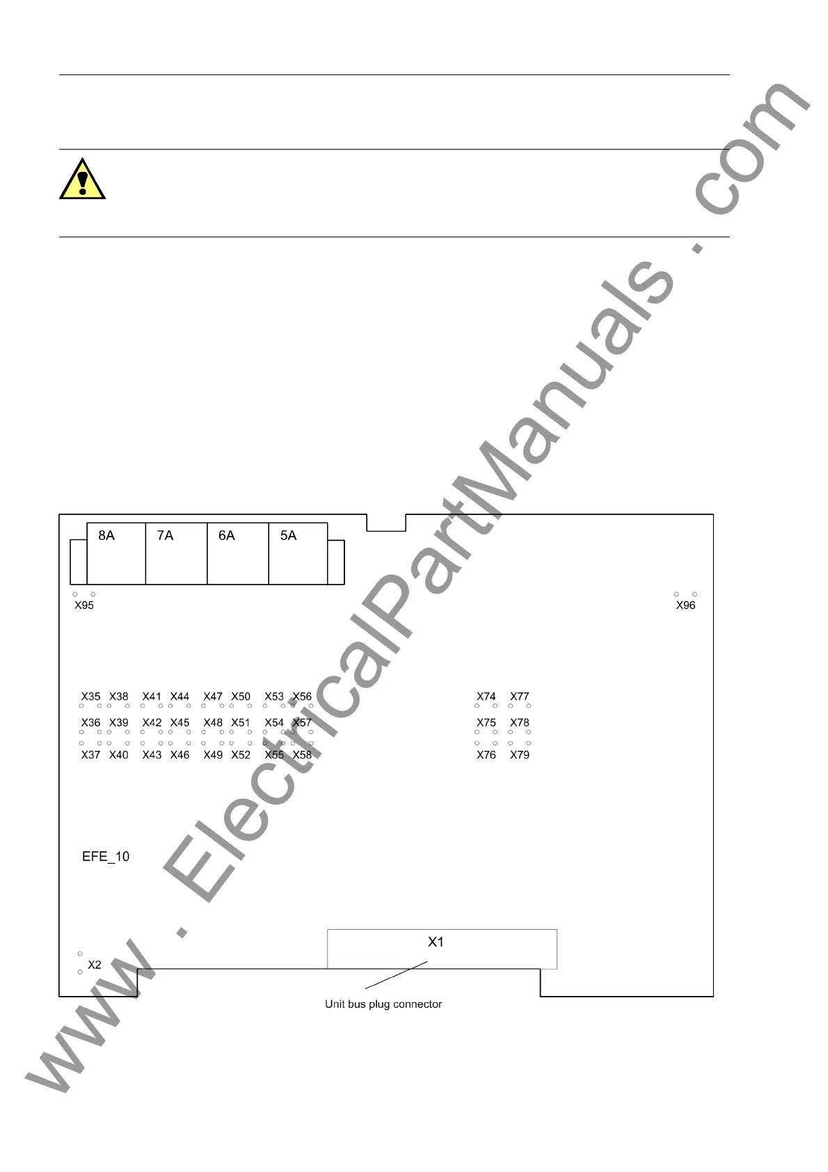
Remove the plug connector X1 to the front plate on the EFE_10 module
(Figure 3-4, page 36) and pull out the module.
Change the rated control voltages of the binary inputs to the desired settings, see
Figure 3-4, page 36 and Table 3-4, page 37.
To insert the buffer battery into the bay unit:
Press the battery firmly into its snap-in holder (see Figure 2-5, page 20) on the PFE/
SVW module. Observe the correct battery polarity! The polarity is marked on the
back of the board.
Figure 3-4 Location of the jumpers on the EFE_10 module (bay unit 7SS525)
Warning!
Dangerous voltages may be present inside the device!
Make sure to switch the auxiliary voltage off before opening the front panel.
www . ElectricalPartManuals . com
 Loading...


