Motor Description
1.3 Selection and Ordering Data
Synchronous Motors 1FK7
Configuration Manual, (PFK7S), Edition 12.2006, 6SN1197-0AD16-0BP1
19
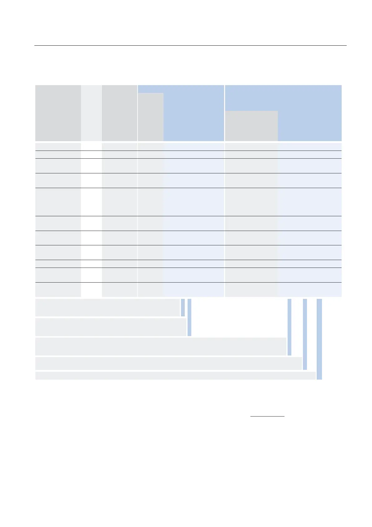
Motor type
(continued)
Static
current
Calculated
power
P
calc
= M
0
x
n
rated
/9550
SINAMICS Motor Module Power cable with complete shield
Motor terminal (and brake terminal) via
power connector
Rated
output
current
I
0
at M
0
∆
T=100 K
P
calc
for M
0
∆
T=100 K
I
rated
Order No.
For complete order no.,
see “SINAMICS S120”
Power
con-
nector
Motor
cable cross
section
7)
Order no.
Pre-assembled cable
A kW/HP A Size mm
2
1FK7105-5AC71... 20 10/13.4 30 6SL312 7 - 7 TE23-0AA. 1.5 4 x 2.5 6FX 7 002-5 7 S31-....
1FK7042-5AF71... 2.2 0.9/1.2 3 6SL312 7 - 7 TE13-0AA. 1 4 x 1.5 6FX 7 002-5 7 S01-....
1FK7060-5AF71...
1FK7063-5AF71...
4.5
8
1.9/2.6
3.5/4.7
5
9
6SL312 7 - 7 TE15-0AA.
6SL312
7 - 7 TE21-0AA.
1
1
4 x 1.5
4 x 1.5
6FX 7 002-5 7 S01-....
6FX
7 002-5 7 S01-....
1FK7080-5AF71...
1FK7083-5AF71...
4.8
10.4
2.5/3.4
5.0/6.7
5
9
6)
6SL312 7 - 7 TE15-0AA.
6SL312
7 - 7 TE21-0AA.
1
1
4 x 1.5
4 x 1.5
6FX 7 002-5 7 S01-....
6FX
7 002-5 7 S01-....
1FK7100-5AF71...
1FK7101-5AF71...
1FK7103-5AF71...
1FK7105-5AF71...
11.2
19
27.5
31
5.7/7.6
8.5/11.4
11.3/15.2
15/20.1
18
18
6)
30
30
6)
6SL312 7 - 7 TE21-8AA.
6SL312
7 - 7 TE21-8AA.
6SL312
7 - 1TE23-0AA.
6SL312
7 -1TE23-0AA.
1
1.5
1.5
1.5
4 x 1.5
4 x 2.5
4 x 4
4 x 10
6FX 7 002-5 7 S01-....
6FX
7 002-5 7 S31-....
6FX
7 002-5 7 S41-....
6FX
7 002-5 7 S61-....
1FK7060-5AH71...
1FK7063-5AH71...
6.2
12
2.8/3.8
5.2/7.0
9
18
6SL312 7 - 7 TE21-0AA.
6SL312
7 - 7 TE21-8AA.
1
1
4 x 1.5
4 x 1.5
6FX 7 002-5 7 S01-....
6FX
7 002-5 7 S01-....
1FK7080-5AH71...
1FK7083-5AH71...
7.4
15
3.8/5.1
7.5/10.1
9
18
6SL312 7 - 7 TE21-0AA.
6SL312
7 - 7 TE21-8AA.
1
1
4 x 1.5
4 x 1.5
6FX 7 002-5 7 S01-....
6FX
7 002-5 7 S01-....
1FK7011-5AK71...
1FK7015-5AK71...
1.5
1.5
0.11/0.2
0.22/0.3
3
3
6SL312 7 - 7 TE13-0AA.
6SL312
7 - 7 TE13-0AA.
0.5
0.5
4 x 1.5
4 x 1.5
6FX5002-5DA20-....
6FX5002-5DA20-....
1FK7022-5AK71... 1.8 0.5/0.7 3 6SL312 7 - 7 TE13-0AA. 1 4 x 1.5 6FX 7 002-5 7 S01-....
1FK7032-5AK71...
1FK7034-5AK71...
1.7
1.9
0.7/0.9
1/1.3
3
3
6SL312 7 - 7 TE13-0AA.
6SL312
7 - 7 TE13-0AA.
1
1
4 x 1.5
4 x 1.5
6FX 7 002-5 7 S01-....
6FX
7 002-5 7 S01-....
1FK7040-5AK71...
1FK7042-5AK71...
2.25
4.4
1.0/1.3
1.9/2.6
3
5
6SL312 7 - 7 TE13-0AA.
6SL312
7 - 7 TE15-0AA.
1
1
4 x 1.5
4 x 1.5
6FX 7 002-5 7 S01-....
6FX
7 002-5 7 S01-....
Cooling:
Internal air cooling
External air cooling
0
1
Motor Module:
Single Motor Module
Double Motor Module
1
2
Power cable model:
MOTION-CONNECT 800
MOTION-CONNECT 500
8
5
Without brake cores
With brake cores
C
D
For length code as well as power and signal cables, see “MOTION-CONNECT cables and connections”. ....
1)
If the absolute encoder is used, M
rated
is reduced by 10%.
2)
These values refer to n = 2500 rpm.
3)
These values refer to n = 4000 rpm.
4)
These values refer to n = 3500 rpm.
5)
These values refer to n = 5000 rpm.
6)
With the specified Motor Module, the motor cannot be utilized with
M
0
at ∆T = 100 K winding temperature rise. If a Motor Module with a
higher rating is used, you must check whether the specified power
cable can be connected to it.
7)
The current carrying capacity of the power cables corresponds to
IEC 60204-1 for type of routing C under continuous operation condi-
tions with an ambient air temperature of +40 °C (104 °F), designed
for I
0
(100 K), PVC/PUR-insulated cable.
8)
Motors in shaft height 20 are not available with a DRIVE-CLiQ inter-
face. The encoder systems are connected via the SMC (Sensor
Modul Cabinet-Mounted).
 Loading...


