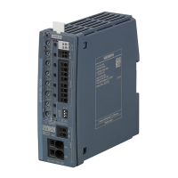
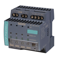
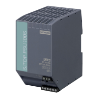
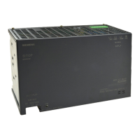
Description, device design, dimension drawing
2.4 Status displays and signaling
SITOP SEL1200-1400
Equipment Manual, 06.2020, A5E46496083-2-76
17
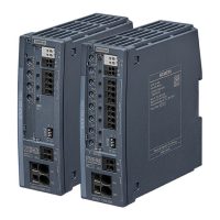
Indicator light (LED 1 - 4 (1 - 8)) ⑥, signaling contact (13, 14) ④ and selector switch for
diagnostics interface (COM) ⑦
6EP4437-7FB00-3DX0
6EP4437-7FB00-3CX0
6EP4438-7FB00-3DX0
6EP4437-7EB00-3DX0
6EP4437-7EB00-3CX0
6EP4438-7EB00-3DX0
Off All LEDs:
• No supply voltage
• Device powering up: After the device has powered up, the out-
puts are switched on, taking into consideration the switch-on de-
lay that has been set.
LED, individual output:
Output defective (internal fuse has ruptured)
Normal operation, output is switched on
Flashes green The output current is in the overload range according to the shut-
down characteristic (see Chapter Electronic overload shutdown and
reset (Page 21))
Overload at the output: Output current 100 - 150 % of the response
threshold (permissible for 5 s)
Flashes orange
Output manually switched off using pushbutton (ON/OFF/RST)
⑥:
The state is saved when the device is switched off, and can only be
reset again by pressing the up button again.
Lights up red
Output is automatically shut down due to overload or external over-
voltage > typ. 30 V/100 ms. The output can be switched on again
after a typical wait time of 20 s. The wait time still to elapse is saved
when switching off the device – and is reactivated after the device
has been switched on again.
Flashes red
Output ready to be reset after an automatic switch off by actuating
the (ON/OFF/RST) ⑥ or remote reset (RST) ④ (effective for all
outputs that have been automatically switched off)
...
all LEDs indi-
vidually flash
Overload - total max. output current exceeded, after max. 30 s out-
puts are successively switched off (4 → 3 → 2 → … (8 → 7 → 6 → …))
until there is no longer an overload condition.
Red running
Device overtemperature: The outputs can be switched-on again once
the temperature is in the normal range.
Contact (13, 14) (NO con-
tact):
Contact rating: 24 V AC/0.1 A; 30 V DC/0.1 A
NOTICE: It is not permissible that the signaling contact is connected
to the line voltage!
closed
:
for COM = '0': all outputs active
for COM = '1': Data transfer
Selector switch for diagnostic
interface (COM)
Switchover between signaling the status of the output channels and
communication at the signaling contact.
'0': Displays the status of the output channels
'1': Internal device parameters are transferred via the signaling con-
tact
'1' = 24 V DC / '0' = 0 V (pull down)
 Loading...
