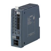
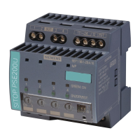
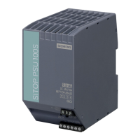
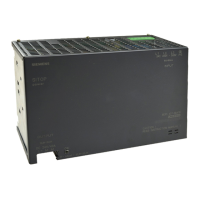
Description, device design, dimension drawing
2.4 Status displays and signaling
SITOP SEL1200-1400
16 Equipment Manual, 06.2020, A5E46496083-2-76
2.4 Status displays and signaling
6EP4437-7FB00-3DX0
6EP4437-7FB00-3CX0
6EP4438-7FB00-3DX0
6EP4437-7EB00-3DX0
6EP4437-7EB00-3CX0
6EP4438-7EB00-3DX0
Group signal contact (13, 14)
floating relay contact (NO contact),
contact rating: 24 V AC/0.1 A; 30 V DC/0.1 A
NOTICE: It is not permissible that the signaling contact is connected to the line
Remote reset (RST)
non-isolated 24 V DC input
Signal level "High" for > 15 V
Indicator light and pushbutton
(ON/OFF/RST) for each output
Three-color LED: rot, green and orange
Selector switch for diagnostic interface
(COM)
Switchover between signaling the status of the output channels and communi-
cation at the signaling contact.
Figure 2-4 Status displays and signaling
The operating state of the outputs is displayed using multi-color LEDs at the front of the
device. Symbols indicate the significance of each LED, which are listed in the following table.

 Loading...
