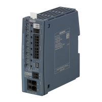
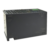
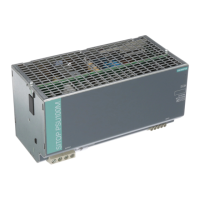
Description, device design, dimension drawing
2.4 Status displays and signaling
Selectivity modules
18 Manual, 01.2017, C98130-A7579-A1-2-7629
1*
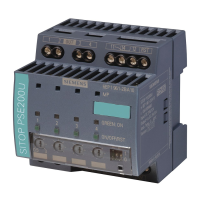
The status of all four outputs is serially signaled using status output ④ (see Figure 2-5
Status signaling (Page 18)). A frame comprises a start bit START and four status bits Ci
(i=1 … 4), which are each separated by a pause bit P. While the device powers up, or if the
supply voltage is missing, nothing is signaled, the status remains continuously at ’0’. For
SIMATIC-S7 controllers (S7-300/400/1200/1500), a function block for evaluation is available
under (http://www.siemens.com/sitop
) or the direct link
(https://support.industry.siemens.com/cs/us/en/view/61450284).
Figure 2-5 Status signaling
 Loading...
