28
MAN-100411
SITRANS LVL200E - Operating Instructions
55328-EN-170712
3
2
1
16 ±1,5
I/mA
8
±1,5
< 3,6
0,6
±0,2 1,5 ±0,51,5 ±0,5
t/s
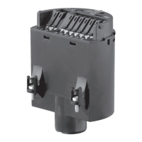
Fig. 29: Flow chart of the function test
1 Fault message
2 Empty signal
3 Full signal
Check if all three switching conditions occur in the correct sequence
and the stated time period. If this is not the case, there is a fault in the
measuring system (see also the operating instructions manual of the
signal conditioning instrument). Keep in mind that connected instru-
ments are activated during the function test. By doing this, you can
check the correct function of the measuring system.
Note:
Keep in mind that the starting time t
A
of the voltage supply can extend
thetimeuptotherstswitching(e.g.SITRANSSCSC,SITRANS
TCSC +1 s)
Test procedure
After releasing the button or after a brief line break.
Sensor
current -
Sensor
Level relay
A-overll
protection
Signal lamp
A-Overll
protection
Level relay
B - dry run
protection
Signal lamp
B - Dry run
protection
Fail safe
relay
Control
lamp
1. Fault sig-
nal
0.6 s
(±0.2 s)
+ t
A
1)
< 3.6 mA currentless currentless currentless
2. Empty
signal
1.5 s
(±0.5 s)
8 mA
(±1.5 mA)
energized currentless energized
3. Full signal
1.5 s
(±0.5 s)
16 mA
(±1.5 mA)
currentless energized energized
1)
Starting time of the voltage supply
 Loading...