Siemens 7482255 Rev 01 Page 11 of 52
October 2002
Chapter 4 - Removing and Replacing Spare Parts
3. Remove the four M3 X 8 binding head screws and external lock washers
from the mounting plate, to separate the mounting plate from the P91W.
3.3 Installing the Black and White Printer
Perform the following steps to install the black and white printer in the G50 or
the G60 S system.
1. Turn off the system and unplug the power cable from wall outlet.
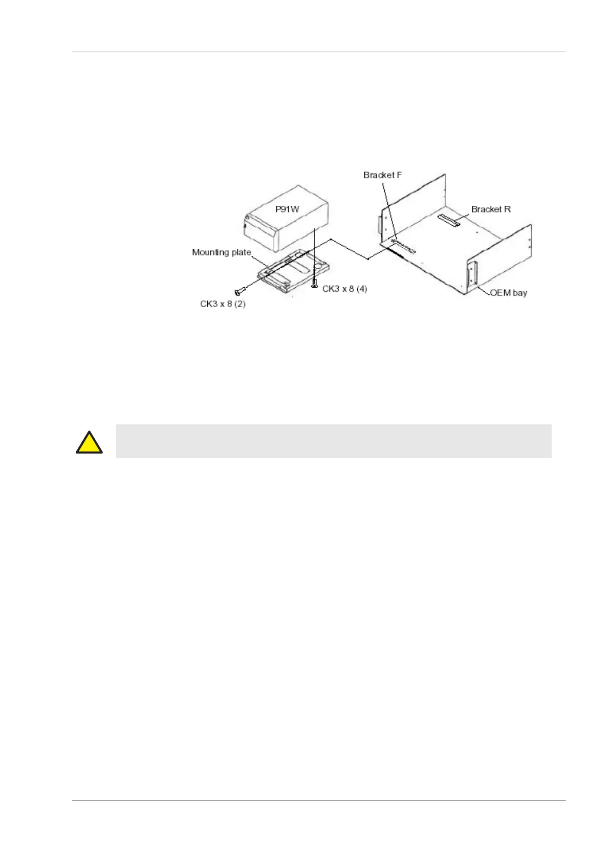
2. Attach the mounting plate to the bottom of the P91W printer using the four
M3 X 8 binding head screws and external lock washers as shown in
Figure 4-10.
3. Set the number 1 DIP switch shown in Figure 4-11 in the On (upward) posi-
tion; set the remaining switches to Off (downward).
4. Attach all of the cables shown in Figure 4-11 to the rear of the P91W as you
insert it into the OEM bay.
Figure 4-10 Printer Removal from the OEM Bay
The screws designated as CK3x8 in Figure 4-10 are M3x8 binding
head screws with external lock washers.
!
Warning: Use threaded fasteners of the length cited here to avoid damaging or shorting under-
lying equipment.
 Loading...