EasyManua.ls Logo

Siemens SSC Series User Manual

Siemens SSC Series
5 pages
To Next Page IconTo Next Page
Page #1 background imageLoading...
Page #1 background image
Installation Instructions
Document No. 129-253
May 8, 2019
SSC Series Electronic Valve Actuator
Item Number 129-253-07, Rev. FA Page 1 of 5
Product Description
The SSC series actuator requires a 24 Vac, Class 2
supply and provides a 0 to 10 Vdc or Floating (three-
position) control signal. The actuator controls a
Powermite 599 Series MT Series valve with a
7/32-inch (5.5-mm) stroke.
Warning /Caution Notations
WARNING:
Personal injury or loss of life
may occur if you do not
perform a procedure as
specified.
CAUTION:
Equipment damage or loss of
data may occur if you do not
follow a procedure as
specified.
Product Numbers
SSC61U 0 to 10 Vdc, proportional control,
non-spring return (fail-in-place)
SSC61.5U 0 to 10 Vdc, proportional control,
spring return (fail-safe)
SSC81U Floating control, non-spring return
(fail-in-place)
SSC81.5U Floating control, spring return
(fail-safe)
Contents
One SSC actuator
Estimated Installation Time
20 minutes
Required Tools
Small Phillips head screwdriver
Small flat-blade screwdriver
Wire stripper
Prerequisites
CAUTION:
Before applying power, make certain a valve is
connected to the actuator.
If applying power to the actuator when a valve is
not connected, the actuator will respond to a
control signal and the shaft will extend until it
reaches its maximum end stop. Thereafter, it will
not respond to any signal.
If this occurs, disconnect the power. Turn the
manual position indicator on the top of the
actuator to the 0 position and verify the actuator
shaft retracts completely. See Figure 4.
Connect a valve to the actuator and reapply the
power. The actuator will return to normal
operation.
Mounting
The vertical position is recommended for mounting
the actuator. See Figure 1.
Figure 1.
Acceptable Actuator Mounting Positions.
CAUTION:
Mount actuator at a 45° angle from vertical when
using on low pressure steam systems to reduce
radiant heat that can damage the actuator.
Question and Answer IconNeed help?

Do you have a question about the Siemens SSC Series and is the answer not in the manual?

Siemens SSC Series Specifications

General IconGeneral
BrandSiemens
ModelSSC Series
CategoryController
LanguageEnglish

Summary

Product Description

Warning and Caution Notations

Details important safety warnings and cautions for potential injury or equipment damage during operation.

Product Numbers

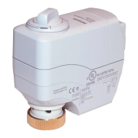
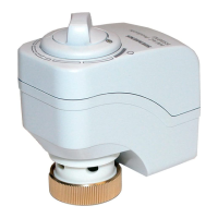
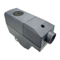
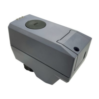
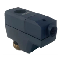
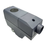
Lists the specific product codes for the SSC series electronic valve actuators.

Contents

Lists the items included in the SSC actuator package.

Estimated Installation Time

Provides an estimated time required for installing the SSC actuator.

Required Tools

Lists the essential tools needed for the installation process.

Prerequisites

Safety Warnings

Critical warnings to follow before performing installation or maintenance procedures.

Operational Cautions

Cautions regarding equipment damage or data loss if procedures are not followed.

Mounting

Recommended Vertical Mounting

Advises on the recommended vertical position for actuator mounting.

45° Angle Mounting Caution

Caution to mount actuator at a 45° angle for low-pressure steam systems to prevent heat damage.

Installation

Removing the Actuator from a Valve

Step-by-step instructions for detaching an SSC actuator from a valve.

Mounting an Actuator on a Valve

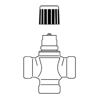
Detailed procedure for attaching the SSC actuator onto a valve.

Tightening Caution

Warning against using tools to tighten the actuator assembly to prevent damage.

Manual Override

Manual Position Adjustment

Instructions on how to manually operate the actuator position using the override knob.

Calibration Stroke

Clearing Calibration Stroke

Procedure to manually clear calibration stroke parameters from nonvolatile memory.

Wiring

Wiring Requirements and Best Practices

Guidelines for wiring conformance to codes, transformer usage, and load limits.

Terminal Wiring Caution

Warning on the critical importance of correct terminal wiring for actuator function and longevity.

Control Signal Limit

Recommendation to limit actuators per single control signal for optimal operation.

Start-up

Verifying Wiring and Position Indicator

Instructions to check wiring and the position indicator during actuator start-up.

Troubleshooting

Connection Verification

Guidance to check wiring for proper connections to resolve issues.

References

Related Technical Instructions

List of relevant technical documents for SSC actuators and related assemblies.

Dimensions

SSC Actuator Dimensional Drawings

Provides detailed dimensions of the SSC actuator in inches and millimeters.

Service Envelope

Minimum Access Space Recommendations

Specifies the minimum recommended clearance space for actuator servicing.

Related product manuals