Do you have a question about the Siemens SSC131.39U and is the answer not in the manual?
Explains the behavior of the SSC131.39U actuator with a 3-position control signal (voltage at Y1/Y2).
Details how the valve opens/closes proportionally to the DC 0-10 V control signal at Y.
Warns about potential personal injury and property damage from non-compliance with national safety regulations.
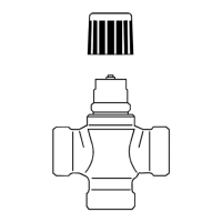
Provides warnings for mounting and instructions on actuator orientation relative to the valve.
Explains that actuators self-calibrate upon receiving operating voltage to find their stroke endpoints.
Details the fail-safe mechanism for SSC161.35U/131.39U, including capacitor charging and return to fail-safe position.
Explains how to move the actuator stem manually using a 3-mm Allen wrench and a button.
Explains how to release the actuator from manual mode, triggering a self-calibration.
Details operating voltage, frequency, power consumption, and fuse/breaker rating for the actuators.
Covers control signal types, input impedance, and limits for parallel operation of actuators.
Describes feedback signal, output current/voltage, resolution, and operating data like positioning force and stroke.
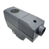
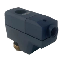
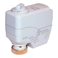
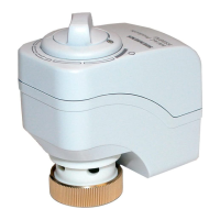
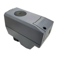
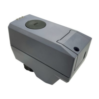
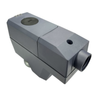
The Siemens Electromotoric Actuator, available in models SSC161.05U, SSC161.35U, and SSC131.39U, is designed for precise control of Powermite MT Series 2-way and 3-way globe valves. These actuators are primarily used in chilled ceiling, VAV, unit ventilators, fan coil units, and other terminal unit applications within building management systems.
The actuators convert an electrical control signal into a mechanical stroke, which is then transmitted to the valve stem to regulate fluid flow. The SSC161.05U (fail-in-place) and SSC161.35U (fail-safe) models operate with a modulating control signal of DC 0...10 V, providing proportional control where the valve opens or closes in proportion to the control signal. At DC 0 V, the actuator stem is retracted, fully closing normally closed valves and fully opening normally open valves. These modulating variants also provide a DC 0...10 V position feedback signal, proportional to the actuator stem's stroke. The SSC131.39U (fail-safe) model uses a 3-position (floating) control signal (AC 24 V). With voltage at Y1, the stem extends; with voltage at Y2, the stem retracts. If no voltage is applied to Y1 or Y2, the actuator maintains its current position. In the event of a power failure, the SSC131.39U actuator fails with the stem fully retracted. All actuators feature self-calibration to the valve stroke, ensuring accurate operation. Modulating variants also provide a position feedback signal.
| Brand | Siemens |
|---|---|
| Model | SSC131.39U |
| Category | Controller |
| Language | English |