EasyManua.ls Logo

Siemens SSC161.05U - User Manual

Siemens SSC161.05U
16 pages
Print Icon
To Next Page IconTo Next Page
Loading...
Electromotoric actuator
SSC161.05U, SSC161.35U, SSC131.39U
For Powermite MT Series 2-way and 3-way globe valves
SSC161.05U (fail-in-place), and SSC161.35U (fail-safe): Operating voltage AC/DC
24 V, modulating control signal DC 0...10 V
SSC131.39U (fail-safe): Operating voltage AC 24 V, 3-position (floating) control
signal
All actuators are self-calibrating to the valve stroke
Modulating variants have position feedback signal
Direct mounting with coupling nut, no tools required
Manual override
Position and actuator motion indication (LED)
Positioning force 67 lbf (300 N)
Parallel operation of multiple actuators possible
A6V12681517_enUS_a
Smart Infrastructure
02/09/2023
Question and Answer IconNeed help?

Do you have a question about the Siemens SSC161.05U and is the answer not in the manual?

Summary

Use

Technical design

3-position control signal (for SSC131.39 U only)

Details the 3-position control signal for a specific actuator model.

DC 0...10 V control signal

LED indication

Ordering

Delivery

Valve combinations

Product documentation

Notes

Engineering

National safety regulations

Mounting

Commissioning

Self-calibration

Electrical fail-safe function (for SSC161.35 U, SSC131.39 U only)

Manual operation

Cabling operation

Maintenance

Repair

Disposal

Warranty

Open Source Software (OSS)

Technical data

Power supply

Details the electrical power requirements for the actuators.

Signal input

Explains the types of control signals the actuators accept.

Signal output

Describes the feedback signals provided by the actuators.

Operating data

Lists key operational parameters like running speed and force.

Electrical connection (connecting cable integral)

Mounting

Standards

FCC regulations

Statement

General ambient conditions

Material

Weight

Diagrams

Connection terminals

Connection diagrams

Dimensions

Revision numbers

Overview

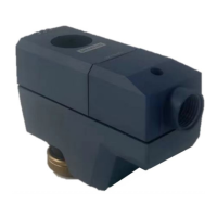
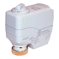
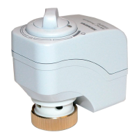
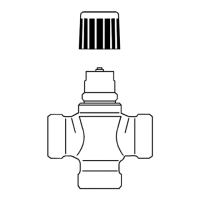
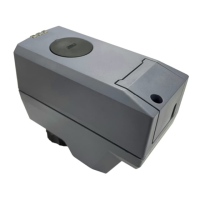
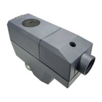
The Siemens Electromotoric Actuator, available in models SSC161.05U, SSC161.35U, and SSC131.39U, is designed for precise control of Powermite MT Series 2-way and 3-way globe valves. These actuators are primarily used in chilled ceiling, VAV, unit ventilators, fan coil units, and other terminal unit applications within building management systems.

Function Description:

The actuators convert an electrical control signal into a mechanical stroke, which is then transmitted to the valve stem to regulate fluid flow. The SSC161.05U (fail-in-place) and SSC161.35U (fail-safe) models operate with a modulating control signal of DC 0...10 V, providing proportional control where the valve opens or closes in proportion to the control signal. At DC 0 V, the actuator stem is retracted, fully closing normally closed valves and fully opening normally open valves. These modulating variants also provide a DC 0...10 V position feedback signal, proportional to the actuator stem's stroke. The SSC131.39U (fail-safe) model uses a 3-position (floating) control signal (AC 24 V). With voltage at Y1, the stem extends; with voltage at Y2, the stem retracts. If no voltage is applied to Y1 or Y2, the actuator maintains its current position. In the event of a power failure, the SSC131.39U actuator fails with the stem fully retracted. All actuators feature self-calibration to the valve stroke, ensuring accurate operation. Modulating variants also provide a position feedback signal.

Important Technical Specifications:

  • Operating Voltage:
    • SSC161.05U, SSC161.35U: AC/DC 24 V (± 15% for AC, ± 20% for DC)
    • SSC131.39U: AC 24 V (± 20%)
  • Control Signal:
    • SSC161.05U, SSC161.35U: Modulating DC 0...10 V
    • SSC131.39U: Floating AC 24 V (3-position)
  • Power Consumption (Normal Operation):
    • SSC161.05U: 3.5 VA (AC); 1.5 W (DC)
    • SSC161.35U: 3.5 VA (AC); 1.5 W (DC)
    • SSC131.39U: 3 VA (AC); 1.5 W (DC)
  • Positioning Force: 67 lbf (300 N)
  • Stroke: 0.05" to 0.25" inch (1.2...6.5 mm)
  • Running Speed (for 5.5 mm stroke):
    • SSC161.05U, SSC161.35U: 5 s/mm (27.5 s ± 25%)
    • SSC131.39U: 16 s/mm (88 s ± 25%)
  • Permissible Temperature of Medium in Connected Valve: 34 to 248°F (1...120°C)
  • Input Impedance: 100 kOhm
  • Feedback Signal (Modulating Actuators Only): DC 0...10 V (Max. output current 1 mA, Resolution 1:100)
  • Parallel Operation: Max. 10 modulating actuators or 24 floating actuators (provided controller output is sufficient). Note: SSC131.39U floating fail-safe actuators cannot be run in parallel with legacy SSC81.5U actuators. For parallel operation of floating fail-safe SSC actuators, all actuators in parallel must be the same part number.
  • Housing Protection Degree: NEMA 2 / IP20 (EN 60529)
  • Housing Color: 2003, Ti-Gray (Cover/base: PC + ABS)
  • Connecting Nut: Brass, 3/4" inch
  • Dimensions: 104 mm (4.1") length, 49 mm (1.9") width, 95.6 mm (3.8") height
  • Weight:
    • SSC161.05U: 9.7 ounces (276 g)
    • SSC161.35U: 10.5 ounces (298 g)
    • SSC131.39U: 10.5 ounces (298 g)

Usage Features:

  • Direct Mounting: The actuators are designed for direct mounting onto Powermite MT Series valves using a coupling nut, requiring no special tools.
  • Self-Calibration: Upon application of operating voltage, the actuators automatically self-calibrate from fully retracted to fully extended to the setpoint. Correct calibration requires a valve stroke greater than 0.05 inch (1.2 mm). If calibration fails, the actuator attempts another calibration after 10 seconds. After three failed attempts, the stem remains in the extended position.
  • LED Indication: An LED provides visual feedback on the actuator's status, including stem retracting/extending, stem position (H0-H40, H40-H60, H60-H100), fail-safe status, calibration, error, manual operation, and ultra-cap initial charging.
  • Manual Override: A manual override feature allows for manual positioning of the actuator stem using a 3-mm Allen wrench. To engage manual mode, open the cover, press and hold down button (a) for at least three seconds. The actuator will ignore control signals from the controller in this mode. Rotating the Allen wrench (b) clockwise moves the stem down, and counter-clockwise moves it up. To release manual operation, press and hold button (a) again for at least three seconds, initiating a self-calibration.
  • Electrical Fail-Safe Function (SSC161.35U, SSC131.39U only): These models feature an ultra-capacitor that stores energy for fail-safe operation. Upon initial power connection or after a power failure, the capacitor charges for up to 180 seconds, during which the actuator cannot respond to control signals. In the event of a power failure lasting more than 5 seconds, the actuator returns to its fail-safe position within 30 seconds.
  • Cabling Operation: The terminal block is easily accessible by unscrewing the cover and removing the cover. Wires can then be connected or disconnected, and the terminal block and cover re-installed.
  • Commissioning: During commissioning, both wiring and actuator functioning should be checked. The actuator must be commissioned only with a correctly mounted valve in place.
  • Orientation: The actuator should be mounted above horizontal.

Maintenance Features:

  • Maintenance-Free: The actuators are designed to require no maintenance.
  • Repair: The actuators cannot be repaired; if a fault occurs, the complete unit must be replaced.
  • Disposal: The device is considered electronic waste and must be disposed of through appropriate channels, complying with all local and currently applicable laws and regulations.
  • Safety Precautions: During any service work, the operating voltage must be switched off. If necessary, electrical connections should be disconnected from the terminals. It is crucial to observe national safety regulations and avoid using pipe wrenches, pliers, or similar tools, as well as lateral pressure or cable tension on the mounted actuator.

Siemens SSC161.05U Specifications

General IconGeneral
BrandSiemens
ModelSSC161.05U
CategoryController
LanguageEnglish

Related product manuals