Do you have a question about the Siemens SSC161.05UT and is the answer not in the manual?
Lists compatible zone valve types (VVP, VXP, VMP) and 2-/3-port valves for use with the actuator.
Mentions typical applications like chilled ceilings, VAV, and fan coil units.
Details the capability for parallel operation of up to 10 units, provided controller output suffices.
Explains how the actuator responds to DC 0-10V signals and provides feedback.
Details the meaning of LED patterns for status indication during various operations.
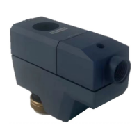
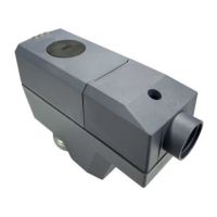
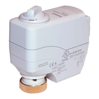
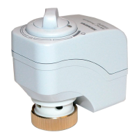
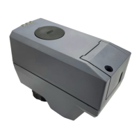
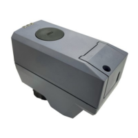
Summarizes key technical specifications and characteristics of the actuator type.
Provides guidance on specifying type and quantity when ordering the actuator.
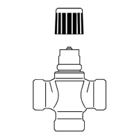
Instructs that valves and actuators must be ordered separately for easier assembly.
Lists compatible valves and their specifications for combination with the actuator.
Outlines requirements for third-party valves to ensure proper operation with the actuator.
Lists compatible controllers for use with the actuator.
References document IDs for mounting instructions, CE and RCM conformity, and environmental declarations.
Provides engineering notes on electrical connections and warnings regarding national safety regulations.
Warns against using improper tools and advises on valve and actuator assembly steps.
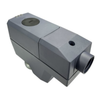
Details the recommended orientation for actuator installation.
Advises on cable handling, temperature observation, power isolation, and magnet damage prevention.
Explains actuator stem movement during commissioning and the requirement for correct valve mounting.
Describes the automatic self-calibration process upon applying operating voltage.
Warns against manual intervention during the self-calibration process.
Explains actions taken if calibration fails, including automatic re-calibration after 10 seconds.
Details how to manually move the actuator stem using an Allen wrench and a button.
Explains how to exit manual operation mode and initiate self-calibration.
Outlines the steps for connecting or disconnecting wiring terminals, including cover removal.
States that the actuators require no maintenance, but safety precautions must be taken.
Guides on proper disposal of the device as electronic waste according to European guidelines.
Clarifies warranty conditions regarding the use of third-party products.
Provides information on Open Source Software licenses used in the device.
Details the power supply requirements including voltage, frequency, and consumption.
Describes the positioning signal input, impedance, feedback signal, and output characteristics.
Lists key operating parameters like running speed, positioning force, and stroke range.
Specifies requirements for electrical connections, including permissible cable length and diameter.
Covers connection to the valve and mounting orientation.
Lists EU conformity (CE), RCM conformity, and UKCA standards with associated document IDs.
Specifies housing protection, protection class, pollution degree, and overvoltage category.
Provides information on environmental compatibility and related declarations.
Details UL approval and FCC/ICES compliance information.
States FCC compliance conditions and specifies housing color and coupling nut material.
Specifies operating, transport, and storage temperature and humidity ranges.
Details permissible atmospheric pressure conditions.
Specifies the material used for the cover/base and the actuator's weight.
Shows the layout of the connection terminals on the actuator.
Provides the electrical wiring diagram for connecting the actuator.
Displays the physical dimensions of the actuator in millimeters.
Lists the actuator type and the revision number it is valid from.
| Type | Controller |
|---|---|
| Model | SSC161.05UT |
| Operating Voltage | 24 V DC |
| Digital Inputs | 16 |
| Digital Outputs | 16 |
| Analog Inputs | 0 |
| Mounting | DIN rail |
| Protection Class | IP20 |
| Input Voltage | 24 V DC |
| Output Current | 0.5 A |