Do you have a question about the Siemens SSB161.05U and is the answer not in the manual?
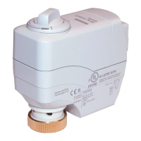
Lists key features like voltage, self-calibration, manual override, LED indication, and positioning force for Powermite MZ Series.
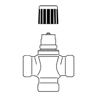
Specifies compatible valve series and model numbers for the actuator.
Lists typical application areas for the actuator, such as chilled ceilings and VAV systems.
Details the parallel operation capability for up to 10 units, contingent on controller output.
Explains how the DC 0-10V signal controls valve stroke and actuator behavior.
Details type, stock number, voltage, speed, stroke time, control signal, and characteristic.
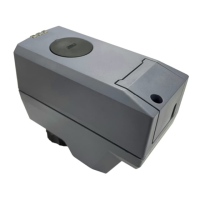
Lists available accessories such as conduit covers.
Provides guidance on how to order the actuator and related items by type and quantity.
Explains factory assembly versus separate ordering of valves and actuators.
Lists combinable 2-way valves for the SSB161.05U, including line sizes, flow rates, and connection types.
Notes on electrical connection requirements in accordance with local regulations and safety precautions.
Warns against using improper tools and applying lateral pressure or tension to the actuator.
Shows graphical instructions for correct actuator orientation during mounting.
States that the actuator must be commissioned only with a correctly mounted valve in place.
Provides notices regarding correct calibration conditions and automatic re-calibration on failure.
Step-by-step instructions for manual stem adjustment using a hex wrench and control button.
Emphasizes switching off operating voltage during any maintenance activities.
Notes for service work, including switching off voltage and disconnecting connections.
Mentions the use of OSS and provides a link to the software license and copyright information.
Details operating voltage, frequency, power consumption, and primary fuse rating.
Covers control signal type, input impedance, and parallel operation limits.
Specifies running speed, positioning force, stroke, and permissible medium temperature.
Lists permissible length for signal lines, wire cross section, and cable diameter.
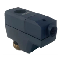
Details connection to valve and orientation.
Lists EU conformity (CE), RCM, UKCA, protection degrees, and pollution degree.
Identifies the terminal labels (G0, Y, G) used for wiring connections.
Illustrates wiring diagrams for connecting the actuator to a controller system.
Shows physical dimensions of the actuator in millimeters and inches.
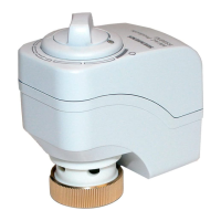
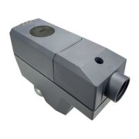
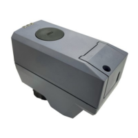
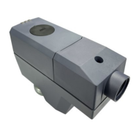
The Siemens SSB161.05U is an electromotoric actuator designed for use with Powermite MZ Series 2-way and 3-way globe valves. This actuator is typically employed in applications such as chilled ceilings, VAV (Variable Air Volume) systems, unit ventilators, fan coil units, and other terminal unit applications.
The SSB161.05U actuator operates with an AC/DC 24 V power supply and responds to a DC 0...10 V positioning signal. When driven by this positioning signal, the actuator produces a stroke that is transmitted to the valve stem, converting it into a mechanical stroke to control the valve stem's position. The actuator is self-calibrating to the valve stroke, ensuring accurate and consistent operation.
The valve's opening and closing are proportional to the control signal Y. At DC 0 V, the actuator stem retracts, causing a normally closed valve to be fully closed and a normally open valve to be fully open. If power is lost, the actuator maintains its current position. The actuator also provides position and motion indication via an LED.
| Brand | Siemens |
|---|---|
| Model | SSB161.05U |
| Category | Controller |
| Language | English |